BTW: have tested clip mount using SK481, MBR40250 and a THFU1. Very hard to insert the clip, even harder to remove it. For the SK489 variant we would need 8 clips ...
BR, Toni
I use clip mounted output devices, and I agree. It's hard to mount, and You need to take it into consideration in the planning phase. I use some tools to remove the force from the PCB.
Sajti
Attachments
Last edited:
...
I use some tools to remove the force from the PCB. ...
Special tools or just standard tools?
Special tools or just standard tools?
This is special, as it was planned especially for SK514, and the pcb I use. I put picture about the pcb above.
Sajti
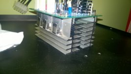
A nice variant for (forced) cooling of small power amplifiers.")
Not very small power amplifier, as it gives about 150W/8ohms, and 250W/4ohms
As I use no insulators for the output devices I can enable the heatsink temperature up to 100C.Sajti
The power de-rating for elevated Tc must be pretty severe !..............the output devices I can enable the heatsink temperature up to 100C..............
SA2014/SA2015/SA2016 power supply ...
Final 2 pin diode variant (MBR40250G) variant ...
IMHO: ready for fab.
Note: Schematics and Gerbers are free to use only for non commercial DIY projects.
WARNING: the circuit is using and providing very high AC and DC voltages and is therefore very dangerous and can be lethal. I am not responsible for any costs, damage and/or injury using these schematics. Do not use this schematics if you do not have the necessary experience and knowledge.
BR, Toni
Attachments
-
sa2014_power_supply_2pin_diodes_small_pcb.zip306.7 KB · Views: 178
-
sa2014_power_supply_2pin_diodes_small_pcb.pdf749.1 KB · Views: 207
-
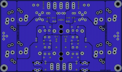 sa2014_power_supply_2pin_diodes_small_pcb_bottom.png613.4 KB · Views: 741
 -
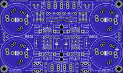 sa2014_power_supply_2pin_diodes_small_pcb_top.png679.8 KB · Views: 846
 -
sa2014_power_supply_2pin_diodes_small_schematic.pdf41.2 KB · Views: 215
-
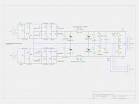 sa2014_power_supply_2pin_diodes_small_schematic.png108.8 KB · Views: 883
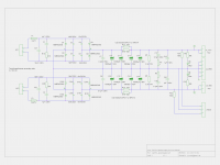
SA2014/SA2015/SA2016 power supply ...
Final 3 pin diode variant (MBR40250TG) variant ...
IMHO: ready for fab.
Note: Schematics and Gerbers are free to use only for non commercial DIY projects.
WARNING: the circuit is using and providing very high AC and DC voltages and is therefore very dangerous and can be lethal. I am not responsible for any costs, damage and/or injury using these schematics. Do not use this schematics if you do not have the necessary experience and knowledge.
BR, Toni
Attachments
-
sa2014_power_supply_3pin_diodes_small_pcb.zip294.4 KB · Views: 139
-
sa2014_power_supply_3pin_diodes_small_pcb.pdf736.7 KB · Views: 174
-
 sa2014_power_supply_3pin_diodes_small_pcb_bottom.png602.5 KB · Views: 281
 -
 sa2014_power_supply_3pin_diodes_small_pcb_top.png669.3 KB · Views: 369
 -
sa2014_power_supply_3pin_diodes_small_schematic.pdf41.2 KB · Views: 182
-
 sa2014_power_supply_3pin_diodes_small_schematic.png108.9 KB · Views: 691
The power de-rating for elevated Tc must be pretty severe !
Not really. The case to sink thermal resistance is much less, than with insulator. So the junction temperature is not higher, comparing to the insulated solution, with 80 degree heatsink.
Sajti
Not really. The case to sink thermal resistance is much less, than with insulator. So the junction temperature is not higher, comparing to the insulated solution, with 80 degree heatsink....
During design I go for max. 55 - 60 degree heatsink temperature - even for summer - so you can touch it with your fingers ...
Using modern keratherm pads you do not have a big thermal loss.
IMHO: the power derating is galactical if you go for 100degree Tc
BR, Toni
I do not believe you.Not really. The case to sink thermal resistance is much less, than with insulator. So the junction temperature is not higher, comparing to the insulated solution, with 80 degree heatsink.
Sajti
20C degrees difference by omitting the insulator ! What were you proposing to use, a sheet of plywood?
What is the power de-rating factor for Tc when heatsink is @ 80°C?
During design I go for max. 55 - 60 degree heatsink temperature - even for summer - so you can touch it with your fingers ...
Using modern keratherm pads you do not have a big thermal loss.
IMHO: the power derating is galactical if you go for 100degree Tc
BR, Toni
The maximum dissipation of each device is about 25W with 4 ohms load. The junction to case thermal resistance is 0.78K/W, and case to sink is 0.1K/W. This is totally 0.9K/W. This means 122.5C maximum junction temperature. The 2SC6145A is rated to 30W at Tj=125C.
In normal music apllication the fan is rarely speed up to the maximum, which means 70C heatsink temperature.
Sajti
OK - you design your cooling with respect to the audio crest factor.
I try to design it - even if many think this is nonsense - for continuous output power.
BR, Toni
Yeah, that is overdesigned, but safe
Sajti
The intermodule connection from PSU to load is the twisted triplet of Vcc+Vee+Zero Volts.You have to understand the route that the current NEEDs to make. Then see where the PCB allows that route to be. Then after you have made that analysis are you ready to offer advice on how he should arrange his traces.
I have not analysed his PCB traces nor the routes that the current needs to flow so I'm not going to offer that advice.
Toni and I found that if you twist Vcc (and Vee) supplies to the amp OPS with the ground wire connecting the OPS to the PSU dirty ground you will have a very noisy amp. Speaker return to PSU dirty ground takes an entirely different path (wire). The wire from the OPS "PWR_GND" is returning bypass cap pulses back to the dirty ground at the PSU.
The principal currents flow from the PSU to the speaker load via the OPS, speaker-out wire and back from the speaker terminals directly to the PSU. Within the PSU there is currently flowing to ground via the caps (main filter, bypass and Zobel).
Why don't you? It will take but a few seconds.
So what is in store for SA2017? Can I be cheeky and suggest:
- 100W@8R/200W@4R (continuous if possible)
- IPS with direct acceptance of balanced input (4 quadrant input stage? ) making my balanced to single-ended input boards redundant
- max dimensions 100mm x 200mm so can (just) fit vertically in 5U case. IPS/VAS can stack over OPS if need be (board to board connector rather than wiring?)
- wrapped in a nice bow
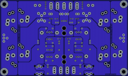
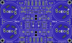
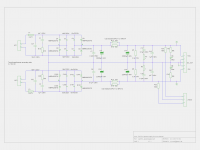
SA2014 power supply reloaded ...
Final 2 pin diode variant (MBR40250G) variant ...
IMHO: ready for fab.
Note: Schematics and Gerbers are free to use only for non commercial DIY projects.
WARNING: the circuit is using and providing very high AC and DC voltages and is therefore very dangerous and can be lethal. I am not responsible for any costs, damage and/or injury using these schematics. Do not use this schematics if you do not have the necessary experience and knowledge.
BR, Toni
Attachments
-
 sa2014_power_supply_2pin_diodes_big_schematic.png113.4 KB · Views: 606
 -
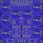 sa2014_power_supply_2pin_diodes_big_pcb_top.jpg885.6 KB · Views: 619
 -
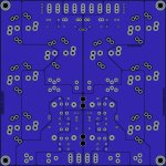 sa2014_power_supply_2pin_diodes_big_pcb_bottom.jpg454.6 KB · Views: 445
 -
sa2014_power_supply_2pin_diodes_big_schematic.pdf42.9 KB · Views: 253
-
sa2014_power_supply_2pin_diodes_big_pcb.pdf939.4 KB · Views: 250
-
sa2014_power_supply_2pin_diodes_big_pcb.zip399.1 KB · Views: 206
Last edited:
- Home
- Amplifiers
- Solid State
- 2stageEF high performance class AB power amp / 200W8R / 400W4R