Nice design Tony, high quality for your hi end amps.
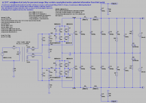
I do not see the schematics for your new PS, you showed it in ltspice. Can you pls, post the sim, I am improving my ltspice knowledge when I run your sims, thx.
...
Thx - also for offer! Attached the simulation file!
")
BR, Toni
Attachments
280mm too long for me. It was that left 1/4 or so of the required board that I was looking at in particular for optimisation. I didn't get so far as to figure out a layout that worked. It is quite possible I would have had to drop the second cap pair after the filter resistors.
(BTW the snubber network and likely your caps across the rectifier diodes can readily be SMD as they don't carry much current.)
What is R5 and R6 in post 1920 (versus R13-16)? Just to allow another package?
For your sim you might want to use a sinusoidal load for more realistic rectifier diode power dissipation, filter cap ripple etc. (A simple bias network and NPN/PNP output pair.)
....
(BTW the snubber network and likely your caps across the rectifier diodes can readily be SMD as they don't carry much current.)
What is R5 and R6 in post 1920 (versus R13-16)? Just to allow another package?
...
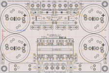
Yes, could be SMD.
R5 and R6 is minimum load for (repair) safety to be sure the big lytics get relatively quickly discharged even if there is no load connected. Could be a vertical wire wound resistor to save pcb space.
Attached another cooling variant using SK489/50
BR, Toni
Attachments
Last edited:
400W into 4r0 is equivalent to passing 10Aac continuously to the dummy load............... I looked at modelled power dissipation in the rectifier diodes even for, say, 400W into 4R continuously (sinusoidal load). It's not that taxing. ..............
The PSU will pass ~150% of that, i.e. 15A on a duty cycle of 50% on each supply rail.
~6W in each rectifier diode.
That is a high heat load.
9.8Arms.
what is the peak current?
what is the average current into the amplifier to allow that peak current to be delivered?
That has to flow through the diodes, but each rail passes that current on alternate half waves. Each diode is on a 50% duty cycle effectively reducing dissipation to 50%.
Your numbers are showing much less than that.
I don't know why our two models are giving such divergent predictions.
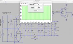
Perhaps have a closer look? This is for the worst two diodes in each bridge. (The attached is slightly understated as I need to refine the load slightly - it generates 9.8Arms across 4R instead of 10Arms. Round the result up.)
Nice idea to add a virtual amplifier!
I have added this to my sim file too.
BR, Toni
BTW: I too get below 2W average dissipation per Diode (peak max 18W dissipation) when virtual amplifier delivers e.g. 400W@4R@40Hz
Attachments
Last edited:
Credit goes to Mark Johnson:
http://www.diyaudio.com/forums/powe...tion-simulating-amp-load-psu.html#post4950581
Note the discussion there about thermal/heatsink demands and whether 2 x 4-diode bridges were worth it...
http://www.diyaudio.com/forums/powe...tion-simulating-amp-load-psu.html#post4950581
Note the discussion there about thermal/heatsink demands and whether 2 x 4-diode bridges were worth it...
Last edited:
I wonder why my simple model is giving a very different diode dissipation from the rest.
Is there a term in the LTspice model that replicates the Amplifier maximum efficiency of a ClassAB power amplifier?
Typically the amplifier efficiency when producing maximum power is around 65%. This gets lower as output power drops.
i.e. maximum input power ~1.5*maximum output power.
Thus a PSU delivering sufficient power has an average current of = ~maximum output power * 1.5 / 40Vac = 15Arms
Not the 10Arms seemingly predicted by the LTspice models you are using.
Or is it the PSU voltage that is increased to give the power delivered to enable the 400W to the load?
"= ~maximum output power * 1.5 / 40Vac = 15Arms" is wrong and should be
= ~maximum output power * 1.5 / 60Vdc = 10Aaverage @ 50% duty on each supply rail.
Last edited:
Peak signal voltage across the load remains the same and of course there is some power supply sag. Perhaps the better place to have this discussion is in the thread I linked to in post 1930. Of course, Toni could link his SA2014 model to his PSU model for more accuracy but I was merely after a proxy for the amp in lieu of a straight resistor/DC draw on the PSU. Note the modelled rms current from the PSU is 7A per rail. I don't have the bias setup properly in my model - I just haven't had the chance to do it properly. If this simple model can be refined for better accuracy without modelling an entire amp I'd be interested in hearing it.
Last edited:
~6W in each rectifier diode.
The total power dissipated by the 4 diodes (combined) is 5.7W in my model...
BTW Toni you might want to give consideration to lifting the values of C1 and C8 (as per your sim) to 1uF. From Mark Johnson (the designer of Quasimodo):
Now you can overdamp the secondary at zeta=2.0 if you wish, and get smooth, smoooooth waveshapes on your Quasimodo.
BTW Toni you might want to give consideration to lifting the values of C1 and C8 (as per your sim) to 1uF. From Mark Johnson (the designer of Quasimodo):
Maybe ... but a 1µF/100V AC part would be a very big component.
The current values (0,1µF in series with 470R) have been measured in real life with scope and 600VA toroid. A real SA2014 Amplifier was connected during measurements.
Note: I have measured with the 10nF capacitors in situ! Maybe you need the big capacitor if you omit all four 10nF caps.
BR, Toni
Last edited:
The total power dissipated by the 4 diodes (combined) is 5.7W in my model...
This is nearly the same I have got during my simulation.
BR, Toni
Maybe ... but a 1µF/100V AC part would be a very big component.
The current values (0,1µF in series with 470R) have been measured in real life with scope and 600VA toroid. A real SA2014 Amplifier was connected during measurements.
Note: I have measured with the 10nF capacitors in situ! Maybe you need the big capacitor if you omit all four 10nF caps.
BR, Toni
Note the optimum value of the snubber resistor will depend on each and every individual transformer used. That's the beauty of Quasimodo. Couple up the particular transformer, slap it so it rings (hence the name) and then damp it with the trimmer resistor - reach optimum damping by looking at scope and then just measure the resistance that twas dialled in. Job done.
I wonder if your board could perhaps allow for TO-220-3 (T suffix MBR40250) TO-220AB case diodes? Note the lower thermal coefficient of the FERD.
Unfortunately not compatible, would require a new pcb design.
BR, Toni
- Home
- Amplifiers
- Solid State
- 2stageEF high performance class AB power amp / 200W8R / 400W4R