Your wife and my wife must be thinking like sisters...On more than one occasion my wife has offered to give away all my audio gear to anyone prepared to come and collect it!

Mostly sport types which I don't like ...Ah but when to come? Late winter for skiing? Summer for fly fishing? Autumn for hunting? You have it all!

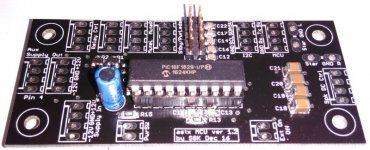
The modified housekeeping firmware is now able to autodetect the different board variants relay control:
Here with my housekeeping v4.3 pcb:
Here with SGK's smd pcb variant:
Here with my housekeeping v4.3 pcb:
powerctl sgk v4.2.560 2017.01.06 16:06:35, (c) 2017, astx@aws-it.at
h=help
ntc type: j=2
temp sensors t,u,v,y,z: 60|60|60|60|60 C
delay repower: m=15000ms
delay in chain: n=0ms
delay inrush: o=250ms
delay mute: p=2000ms
delay dc: s=5000 main loops
invert mute: r=0
invert relay1: 0
invert relay2: 0
power button type: f=1
delay power button: g=300 main loops
h=help
ntc type: j=2
temp sensors t,u,v,y,z: 60|60|60|60|60 C
delay repower: m=15000ms
delay in chain: n=0ms
delay inrush: o=250ms
delay mute: p=2000ms
delay dc: s=5000 main loops
invert mute: r=0
invert relay1: 0
invert relay2: 0
power button type: f=1
delay power button: g=300 main loops
Here with SGK's smd pcb variant:
powerctl sgk v4.2.560 2017.01.06 16:06:35, (c) 2017, astx@aws-it.at
h=help
ntc type: j=2
temp sensors t,u,v,y,z: 60|60|60|60|60 degree C
delay repower: m=15000ms
delay in chain: n=0ms
delay inrush: o=250ms
delay mute: p=2000ms
delay dc: s=5000 main loops
invert mute: r=1
invert relay1: 1
invert relay2: 1
power button type: f=1
delay power button: g=300 main loops
BR, Tonih=help
ntc type: j=2
temp sensors t,u,v,y,z: 60|60|60|60|60 degree C
delay repower: m=15000ms
delay in chain: n=0ms
delay inrush: o=250ms
delay mute: p=2000ms
delay dc: s=5000 main loops
invert mute: r=1
invert relay1: 1
invert relay2: 1
power button type: f=1
delay power button: g=300 main loops
Very cool!
I had a friend over yesterday for another listening session. He is a very critical listener - far more so than me - and had previously been impressed by my system with the Krell FPB-200 driving the main speakers. This time the SA2014 was doing that job. He commented that they clarity of the sound was significantly better than with the Krell. Not a scientific listening test, but something I think you, Toni, can be very proud of. Congratulations!
I had a friend over yesterday for another listening session. He is a very critical listener - far more so than me - and had previously been impressed by my system with the Krell FPB-200 driving the main speakers. This time the SA2014 was doing that job. He commented that they clarity of the sound was significantly better than with the Krell. Not a scientific listening test, but something I think you, Toni, can be very proud of. Congratulations!
Good stuff. What's the current board size? You could simplify by removing the caps across the rectifier diodes (C3-C6 as per schematic in post 1145) which do nothing to snub transformer ringing. You can rely in the snubber networks you added in the final revision to the last board. It would also make sense to provide for Faston .250 tabs in lieu of the screw cage connectors i.e allow choice. The current connectors extend the required area for the PSU as the wires connect laterally. Looks like you have changed to dual full bridge rectifiers which is good. Look into the ST Micro Field Effect Rectifiers e.g. FERD30SM100S. Their Vf is a fraction of the MBR40250G and could allow considerable economy in heat sinking. The other thing worth thinking about is shifting the (0.47R) resistors to after the third main filter cap as it will ease the ripple requirement of these caps. Secondary fuses gone?
Last edited:
Good stuff. What's the current board size?
...
- Board size identical: 150x150mm
- Dual full bridge to avoid DC offsets through toroids.
- The 10nF should stay as close as possible to kill HF ringing.
- FASTON is alternatively possible.
- Half of the caps at output side is to keep the possible peak current as high as possible for the amplifier.
- Fuses are only at toroid input - never had fuses at output of power supply.
FERD30SM100S:
- 30A / 100V
- Vf at 10A Tj 50 degree about 0,5V
- 10 pieces ~ 20EUR
MBR40250:
- 40A / 250V
- Vf at 10A Tj 50 degree about 0,7V
- 10 pieces ~ 15 EUR
BR, Toni
I was hoping it would be smaller - I might want 4 in a case! Taller and narrower better - can fit vertically in a 5U case.
Dual full bridge good.
I don't think the caps across the diodes do anything at all and did not populate them in my build, but if there is room why not allow for them.
However, I think you might find that you can save some board size by optimising heat sinking and diode selection (the 20H are down to 0.45V - more than enough continuous rating and burst). Eur5 = a pint of beer
Yes, that's the trade-off shifting the resistors but high ripple rated caps getting harder to find.
Ah I see the fuses now - doof. I just read C3 and F1 was well obscured and thought you had removed them.
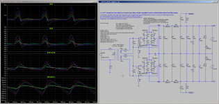
SA2014 power supply reloaded ...
Some simulation results:
Just for a decision if using double filtering makes sense.
Single filter:
.step rfilter1=0 rfilter2=0.235 iload=0.5
Total Harmonic Distortion: 32.443806%(32.590643%)
Vripple+ PP 0.047V
Double filter:
.step rfilter1=0.11 rfilter2=0.11 iload=0.5
Total Harmonic Distortion: 29.466892%(29.628367%)
Vripple PP 0.055V
IMHO: double filtering not worth the extra resistors. Has lower distorted 100Hz harmonics but less output voltage and a bit higher PP ripple voltage.
BR, Toni
Some simulation results:
Code:
Load 0.5A:
=========================================================
.step rfilter1=0        rfilter2=0.11 iload=0.5
        Total Harmonic Distortion: 38.722346%(38.783852%)
        Vripple+ PP     0.068V

.step rfilter1=0.11     rfilter2=0.11 iload=0.5
        Total Harmonic Distortion: 29.466892%(29.628367%)
        Vripple PP      0.055V

.step rfilter1=0        rfilter2=0.235 iload=0.5
        Total Harmonic Distortion: 32.443806%(32.590643%)
        Vripple+ PP     0.047V

.step rfilter1=0.11     rfilter2=0.235 iload=0.5
        Total Harmonic Distortion: 25.453641%(25.848030%)
        Vripple+ PP     0.038V

Load 2A:
=========================================================
.step rfilter1=0        rfilter2=0.11 iload=2
        Total Harmonic Distortion: 32.247965%(32.253499%)
        Vripple+ PP     0.253V

.step rfilter1=0.11     rfilter2=0.11 iload=2
        Total Harmonic Distortion: 24.998663%(25.006082%)
        Vripple+ PP     0.200V

.step rfilter1=0        rfilter2=0.235 iload=2
        Total Harmonic Distortion: 27.177930%(27.186373%)
        Vripple+ PP     0.170V

.step rfilter1=0.11 rfilter2=0.235 iload=2
        Total Harmonic Distortion: 21.690970%(21.702960%)
Vripple+ PP 0.139VSingle filter:
.step rfilter1=0 rfilter2=0.235 iload=0.5
Total Harmonic Distortion: 32.443806%(32.590643%)
Vripple+ PP 0.047V
Double filter:
.step rfilter1=0.11 rfilter2=0.11 iload=0.5
Total Harmonic Distortion: 29.466892%(29.628367%)
Vripple PP 0.055V
IMHO: double filtering not worth the extra resistors. Has lower distorted 100Hz harmonics but less output voltage and a bit higher PP ripple voltage.
BR, Toni
Attachments
I was hoping it would be smaller - I might want 4 in a case! Taller and narrower better - can fit vertically in a 5U case.
...
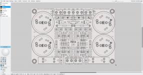
... using other lytics - I have here 22000µF/80V lytics KMH series 105degree. With this big types (40x83mm/ 5Pin) it would be possible to do the same filtering with 4 instead of 8 big parts...
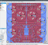
150x100 mm pcb size should be no big problem. See picture.
Have fun, Toni
Attachments
Last edited:
... maybe ready for fab?
- added FASTON 6.35mm as alternative connectors
- Fuseholder 5x20mm or 6x35mm
BR, Toni
Here is where I was heading in my own work on this thus far... I looked at modelled power dissipation in the rectifier diodes even for, say, 400W into 4R continuously (sinusoidal load). It's not that taxing. Does it allow lighter heat sinking which can be re-oriented so as to demand less width? Then run the caps more "in-line" - of course this requires a longer board but I was wondering if it could fit within 20cm length. I didn't get that far as such a board is outside the allowable limits of my Eagle license. I had heard there were going to be big changes to the licensing of Eagle, waited and there were -but I did not like their announcement at all. Hence for me to continue my tinkering I have to learn something like KiCad (or get a student license for Eagle). I was looking at vertically mounted fuse holders as well. FWIW...
Last edited:
Nice design Tony, high quality for your hi end amps.
I do not see the schematics for your new PS, you showed it in ltspice. Can you pls, post the sim, I am improving my ltspice knowledge when I run your sims, thx.
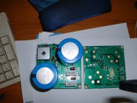
I use the quasimodo to figure out the optimum snubber comps for the selected transformer.
I made a simple un-regulated supply, so it would fit in 100x100mm to get the special pcbway price. Those CDE 382LX 22mF/80V ecaps and the design is about as cheap and easy as you can get. But so many other previous designs were just as simple and worked just fine. PM me for the gerber files if you are interested. I can sent you Tony some pcbs if you want, PM me, gee I even got gold plate for free someone else on the panel wanted IGOBC.
On ecad tools, I was playing around with diptrace, it ain't too bad, I like it better than eagle but each are different. In the PS design I use Orcad16 since I can get things done faster and not need to worry about learning how to drive plus I have years of libraries.
I do not see the schematics for your new PS, you showed it in ltspice. Can you pls, post the sim, I am improving my ltspice knowledge when I run your sims, thx.
I use the quasimodo to figure out the optimum snubber comps for the selected transformer.
I made a simple un-regulated supply, so it would fit in 100x100mm to get the special pcbway price. Those CDE 382LX 22mF/80V ecaps and the design is about as cheap and easy as you can get. But so many other previous designs were just as simple and worked just fine. PM me for the gerber files if you are interested. I can sent you Tony some pcbs if you want, PM me, gee I even got gold plate for free
someone else on the panel wanted IGOBC.On ecad tools, I was playing around with diptrace, it ain't too bad, I like it better than eagle but each are different. In the PS design I use Orcad16 since I can get things done faster and not need to worry about learning how to drive plus I have years of libraries.
Attachments
Last edited:
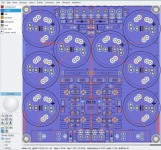
...
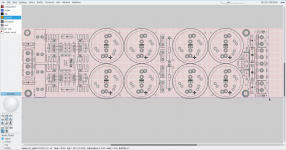
Then run the caps more "in-line" - of course this requires a longer board but I was wondering if it could fit within 20cm length. I didn't get that far as such a board is outside the allowable limits of my Eagle license....
Here an example with lined up lytics ... 280 x 80 mm - too long for my needs but maybe one needs exactly this variant?
BR, Toni
Attachments
- Home
- Amplifiers
- Solid State
- 2stageEF high performance class AB power amp / 200W8R / 400W4R