Fuse!!
I have fuses, many of them!
Fuse on the incoming AC on primary side of three transformers and also fuses on secondary side on each channel. Furthermore fuse on the transformer for relays, signal switch board and volume control.
I reFUSE to have an electronic disaster.
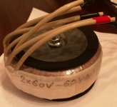
Everything turned out just fine and I have from the transformer 18.93V unloaded from both secondary windings on the transfomer.
Happy again, now I can continue.
Providing you were using the proper fuse the primary should not be damaged.
I have fuses, many of them!
Fuse on the incoming AC on primary side of three transformers and also fuses on secondary side on each channel. Furthermore fuse on the transformer for relays, signal switch board and volume control.
I reFUSE to have an electronic disaster.
Everything turned out just fine and I have from the transformer 18.93V unloaded from both secondary windings on the transfomer.
Happy again, now I can continue.
Hi
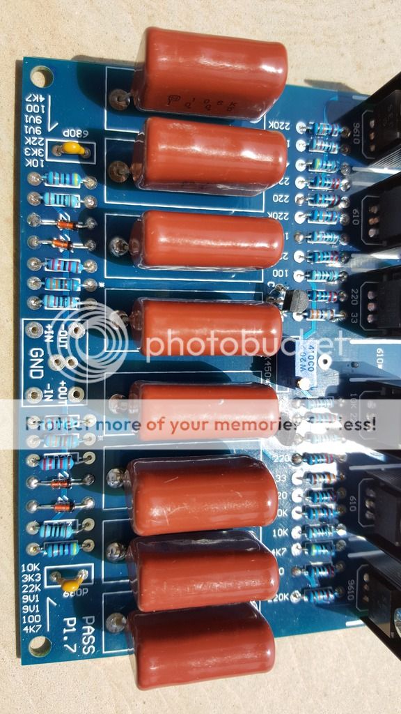
Anyone familiar with this PCB?
I'd like to know a smart option for volume control and the correct use of VR1 2K and VR2, VR3 50R.
I will use it balanced after DAC so only one input.
Thank you!
Anyone familiar with this PCB?
An externally hosted image should be here but it was not working when we last tested it.
An externally hosted image should be here but it was not working when we last tested it.
An externally hosted image should be here but it was not working when we last tested it.
I'd like to know a smart option for volume control and the correct use of VR1 2K and VR2, VR3 50R.
I will use it balanced after DAC so only one input.
Thank you!
boredom to look for bucket pics
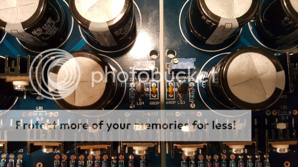
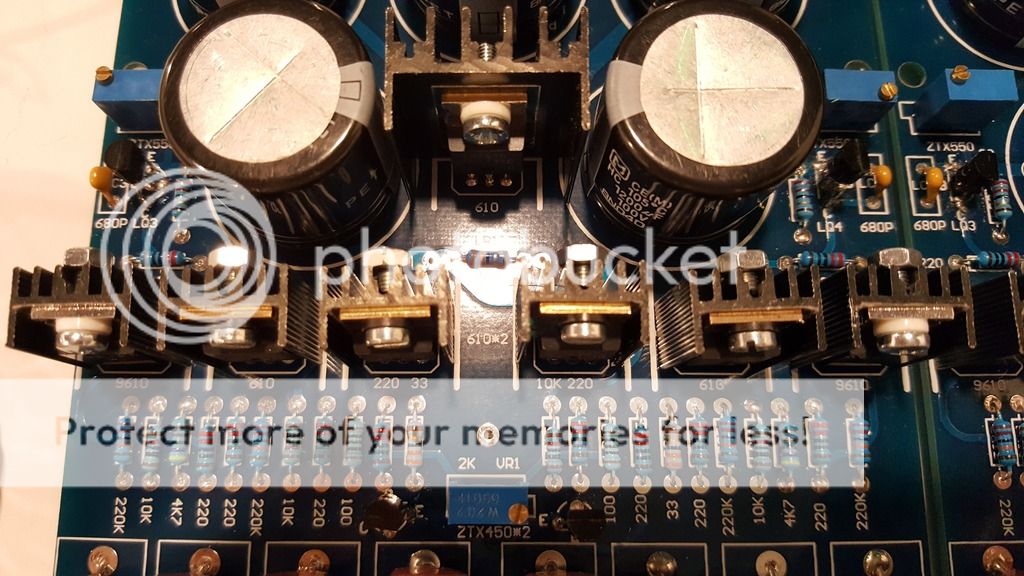
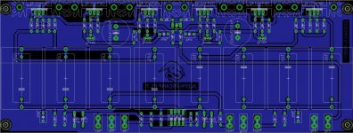
anyway , 2K trimpot is definitelly for gain tweaking , while (by value) 50R trimpots are definitely for fine tuning of Iq , left and right side
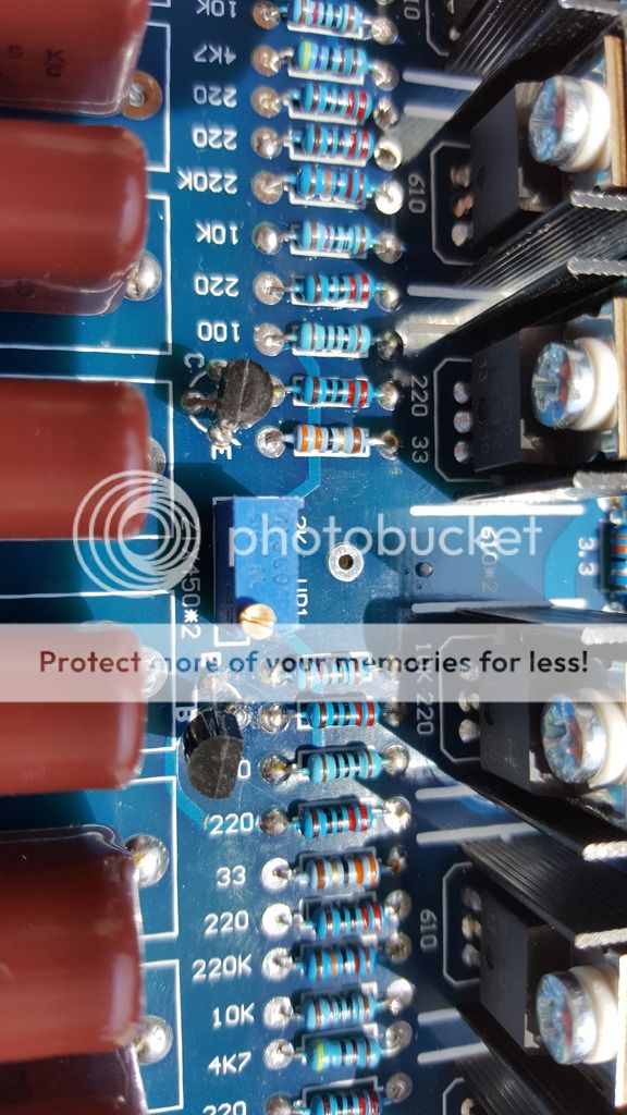
take proper pictures of trimpot area , so we can see few resistors around, to give you some guidelines how to set it
any other text info , besides Pass P1.7 ?
vol pot - same as in original schematic , on output
I would use 4k7 log pot there ........ 10K max.
anyway , 2K trimpot is definitelly for gain tweaking , while (by value) 50R trimpots are definitely for fine tuning of Iq , left and right side
take proper pictures of trimpot area , so we can see few resistors around, to give you some guidelines how to set it
any other text info , besides Pass P1.7 ?
vol pot - same as in original schematic , on output
I would use 4k7 log pot there ........ 10K max.
boredom to look for bucket pics
anyway , 2K trimpot is definitelly for gain tweaking , while (by value) 50R trimpots are definitely for fine tuning of Iq , left and right side
take proper pictures of trimpot area , so we can see few resistors around, to give you some guidelines how to set it
any other text info , besides Pass P1.7 ?
vol pot - same as in original schematic , on output
I would use 4k7 log pot there ........ 10K max.
Thank you!
Hi
Anyone familiar with this PCB?
I'd like to know a smart option for volume control and the correct use of VR1 2K and VR2, VR3 50R.
I will use it balanced after DAC so only one input.
Thank you!
I built an Aleph P 1.7 using a different board setup than yours. On my particular board I had high frequency oscillation problems. This is likely due to the particular board layout. I ended up increasing all the 220ohm gate and base resistors to 680 ohms and adding some bypass capacitors to the bottom side of the 10k resistors that link the + and - current sources. The oscillations were at rf frequencies, about 10mhz, and showed up when the circuitry got up to full temperature and at high signal levels. The lesson here is to thoroughly check the operation with large input signals to verify that you don't have issues like this. This sort of oscillation does not show up as overshoot on square waves which is a standard test for stability but was revealed when large sine wave signals were input to the amp.
One of the central design features of the Aleph P is the output attenuator. The owners manual goes into the reasoning behind this choice. I implemented the stock circuitry for the attenuators and went to work and designed a discrete 7400/4000 series logic controller to adjust the volume using a rotary encoder. I was using this as an exercise to refresh my skills in digital design. This turned out to be quite a challenge and there are a couple of details about the attenuators design that make things more difficult. It would be so much easier to do this with an Arduino. I now have one and am learning how to program it.
The relays I used in the attenuator were not a good choice. They have contact bounce which can lead to clicks and pops when changing levels. Because the full unattenuated preamp output is on the input of the attenuator the pops can be quite loud at times. I dealt with this by using an analog switch to mute the output for a few milliseconds while the relays are switching. A kludge of a solution, but it works for me. Another issue is that using all 256 steps makes for a lot of turning of the volume control to get where you need to be. I added a power on preset for the volume counter to partially deal with that issue. As you can see, there are a lot of issues to deal with for a discreet logic solution. This is the sort of stuff that is much easier to deal with using a micro controller like the Arduino.
The problem with using a typical 50k volume pot on the output is that your output impedance will be high at certain settings. Since the output impedance of the amp circuit is about 2k ohms you are relying on the attenuation factor to give you a reasonably low output impedance. You need to look at the gain structure of your system and match it to the gain and attenuation settings on the preamp in order to get the most out of the dynamic range of the circuit. Good luck with whatever you decide to implement.
Last edited:
.....
Thank you!
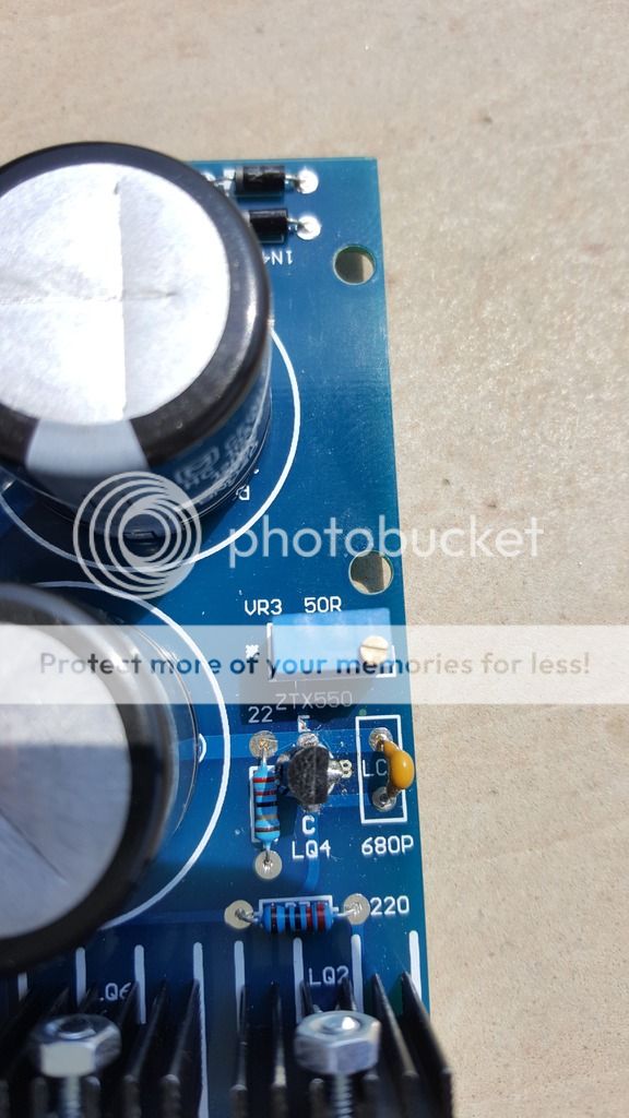
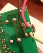
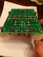
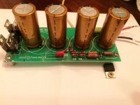
give me exactly same angle, but underside of that last one picture (showing 50R trimpot)
be sure that (LQ2) mosfet pins are also visible
give me exactly same angle, but underside of that last one picture (showing 50R trimpot)
be sure that (LQ2) mosfet pins are also visible
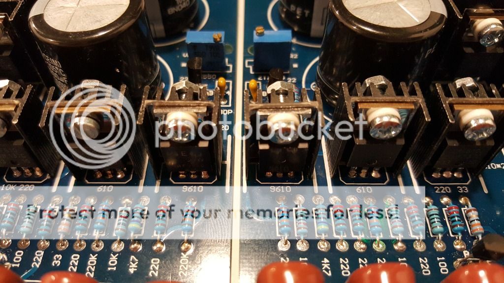
I used BC546/556 instead of ZTX450/550
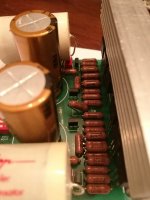
The 50 ohm pots look like they could be in the upper 30ma current source circuit. They may be for adjusting the current which will also adjusts the DC output bias on the output. You could easily check this with measurements. There really aren't that many spots in the circuit where a low 50 ohm pot value makes sense.
I'm asking to see traces , to be able to tell where exactly to measure , while setting with trimpots
Thank you!
set trimpot to have 400 to 450mV across adjacent 22R resistor , and to have same reading on all 22R resistors
or , even better approach, set them (trimpots) to have approx. half of Vcc at inside sides of output caps ( at drains of input mosfets)
Thank you!
Hi there,
this was most recent topic/post regarding aleph p1.7, so instead of opening a new topic I choose to continue this one..
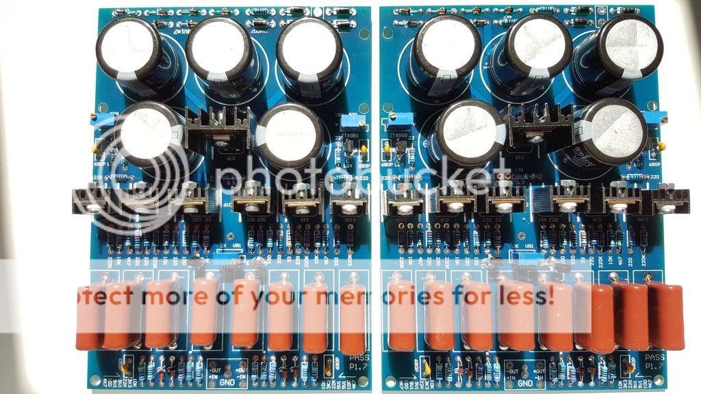
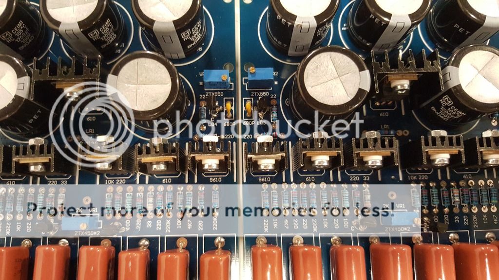
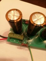
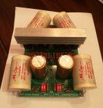
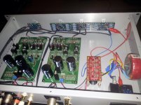
Anyway, thanks to local diy audio member, I acquired disassembled aleph p1.7 (not literally, just PCB's are not connected).
Preamp was working, it was just replaced with valve preamplifier, and box/case reused.
So before connecting it all together, any hint, advice, measurements?
And yes, I am missing (sort of, it was diy project which need more attention than rest of preamp) volume control, and finding some 4 track locally is a challenge, I may be forced to put 2 stereo pots.
If I understand correctly, I need some lower value, ie 2k or 5k?
Also, there are some "things" on preamp boards needing attention (like instead of trimmer there is fixed resistor, previous owner sad he did it the right way (once adjusted he replaced trimmer with resistor).
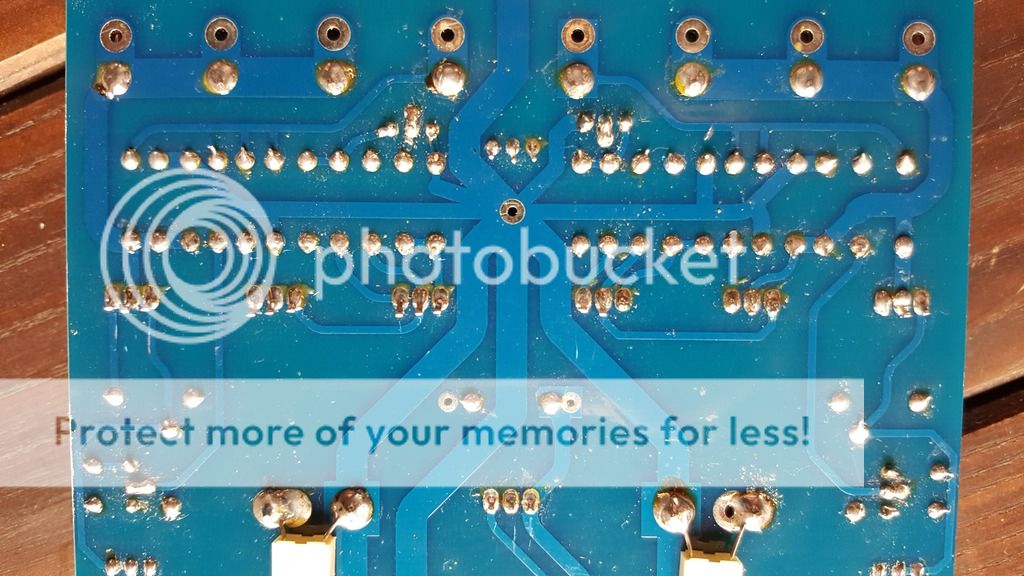
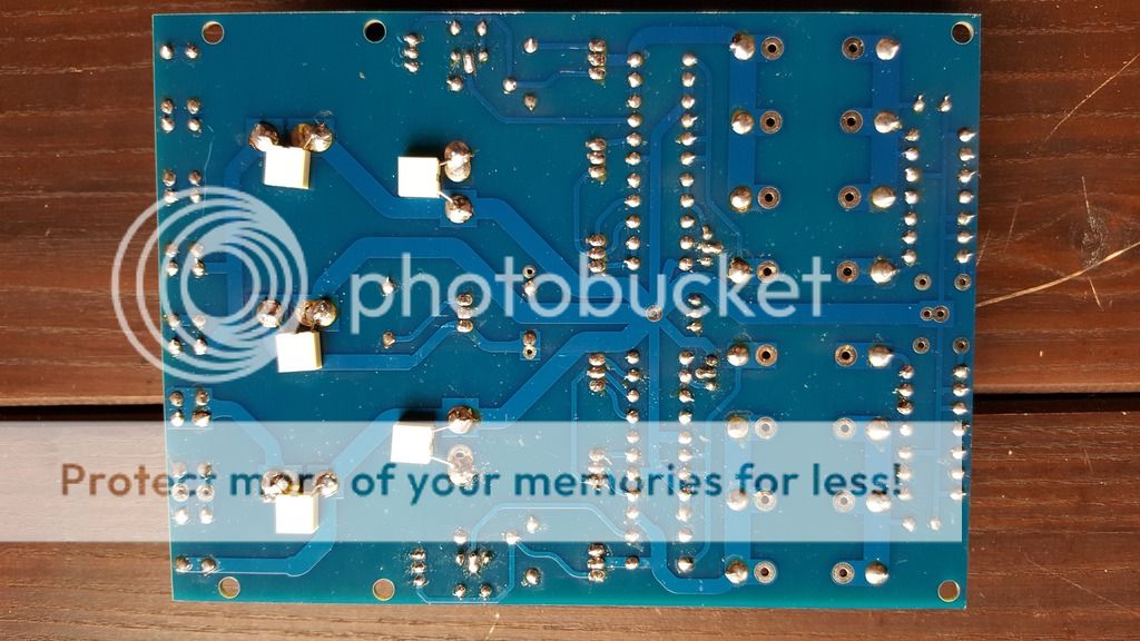
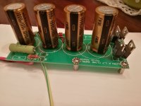
Some photos enclosed (I have lowered resolution, but have hi-res is someone needs it.
Thanks!
this was most recent topic/post regarding aleph p1.7, so instead of opening a new topic I choose to continue this one..
Anyway, thanks to local diy audio member, I acquired disassembled aleph p1.7 (not literally, just PCB's are not connected).
Preamp was working, it was just replaced with valve preamplifier, and box/case reused.
So before connecting it all together, any hint, advice, measurements?
And yes, I am missing (sort of, it was diy project which need more attention than rest of preamp) volume control, and finding some 4 track locally is a challenge, I may be forced to put 2 stereo pots.
If I understand correctly, I need some lower value, ie 2k or 5k?
Also, there are some "things" on preamp boards needing attention (like instead of trimmer there is fixed resistor, previous owner sad he did it the right way (once adjusted he replaced trimmer with resistor).
Some photos enclosed (I have lowered resolution, but have hi-res is someone needs it.
Thanks!
Attachments
I see ...... fixation on original parts - Dales and ZTX
always funny , when European guys are in question
regarding pot - some prefer to use pot where Papa put it (was it 5K on output ?), some prefer to install regular valued pot (25Klog , for instance) in more common position - preceding preamp stage
if you pount me to exact schmtc (on which pcbs are based) , I can tell you what's important to check
I used the Glassware Select 2 input selector and balanced stepped attenuator. They are good sounding, come with decent resistors and are quite inexpensive. I am pretty sure I put mine on the input side, my speakers are low efficiency and the 1.7 boards are dead quiet.
Attenuators and Signal Selecters
Attenuators and Signal Selecters
Attachments
Last edited:
- Home
- Amplifiers
- Pass Labs
- Pass Aleph P 1.7 preamp builders thread