Thanks Mark, I will look into that (on first glance, Balanced stereo attenuator is not available, I can always send an email).
@Zen Mod:
as I have found out, boards are made by diy audio member - veteran (10-ish years ago).
I can only guess that board was following original design, but, maybe, some of older members of forum can confirm (I think "veteran" is not active any more?).
As for pot (or any kind of attenuator..) I would like to follow Mr. Pass ideas.
Thanks
Hi ZM,
Hope it helps!
Pleas take a look here:if you pount me to exact schmtc (on which pcbs are based) , I can tell you what's important to check
An externally hosted image should be here but it was not working when we last tested it.
for big klick hereHope it helps!

.... had them in pc , dunno who made them , lazy to look at
Attachments
thank you.... had them in pc , dunno who made them , lazy to look at
Hi,
as mentioned before, I got P1.7 "in peaces" :.
Anyway, this is volume control, and it should work. I got some basic info, schematics and I manged to find other missing informations (pic, rotary encoder..).
My problem is - it is too big. Previous owner had it in two cases, I am not willing to do the same, so volume control has to be smaller.
Anyway, it is fairly simple design, and, if anything else fails I will do it on vero (strip) board.
However, if there is PCB for relay part already done, please point me to it.
I can (and it is a plan) to move rotary encoder in front, and driver transistors with relays on back - I even considered 2 banks of 8 relays (so on two "floors).
Suggestions for PCB welcomed!
Thanks
as mentioned before, I got P1.7 "in peaces" :
.Anyway, this is volume control, and it should work. I got some basic info, schematics and I manged to find other missing informations (pic, rotary encoder..).
My problem is - it is too big. Previous owner had it in two cases, I am not willing to do the same, so volume control has to be smaller.
Anyway, it is fairly simple design, and, if anything else fails I will do it on vero (strip) board.
However, if there is PCB for relay part already done, please point me to it.
I can (and it is a plan) to move rotary encoder in front, and driver transistors with relays on back - I even considered 2 banks of 8 relays (so on two "floors).
Suggestions for PCB welcomed!
Thanks
Attachments
Slight (understatement) hum after applying volume control
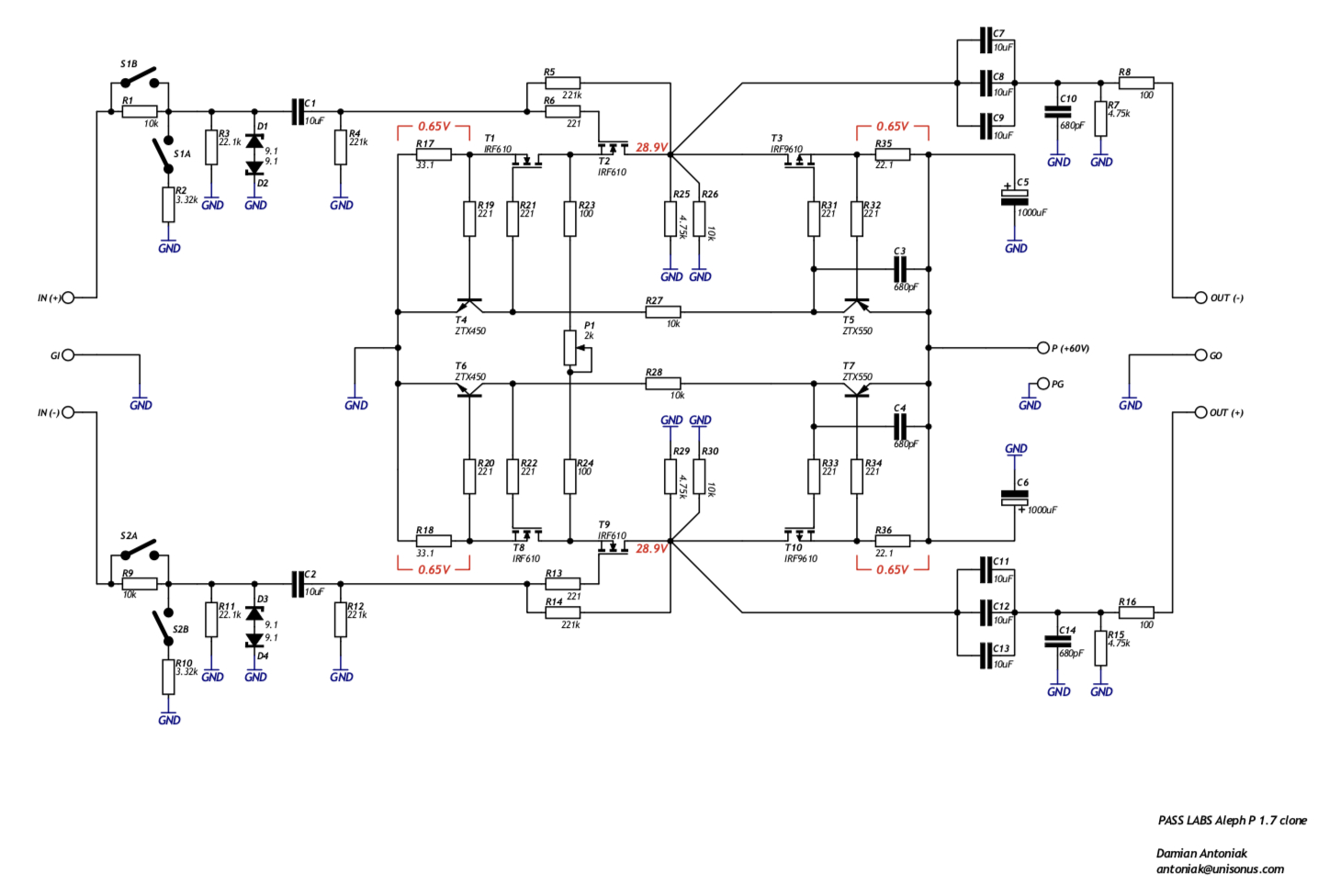
I have built the Aleph P1.7 from Kojas pcb and after some fiddeling around with the boards I got it working and it does play music. It was a real wow when I got it working so I am really happy, but now I have another problem.
When I did put it up on a plywood to see so everything was working out I had it connected with an ordinary 10 kOhm potentiometer and the preamp was singing. Next step was to connect the 128 step relay controlled volume control and what a disappointment. It is humming like a, I don't know but it is humming loud so I seem to have a major ground problem.
The shematics are as follows:
View attachment 128 steps unbalanced attenuator Sch.pdf
I have been thinking cause the rectifier is suited for a center tapped transformer and since my transformer is using 2 x 15-0 volt I am missing the centertap. I asked the seller (Jims Audio) but they were absolutely certain that I could use my transformer and connect one cable to AC and the other to ground but I am not so sure cause that mean that I have a ground that is pulsating with 50Hz and that is what is causing the hum (I presume(nae, I am pretty sure)) cause the ground don't come to 0V with that setup.
Next possibility is to remove the diodes from the rectifier on the pcb and jump these and move the rectifier outside the pcb on a separate board where I can put an ordinary bridgerectifier and then feed the volume control with 15 rms VDC directly.
So here is my question, is it ok to put jumpers instead of the rectifying diodes and then feed 15 rms VDC direct to the AC/Gnd connector that will now be DC/Gnd and still have the LM7812 regulator on the pcb or should I move the regulator as well and feed the volume control with regulated 12 volt DC only??
I don't mind moving the whole regularor outside also cause then I can feed both the source switch pcb and volume control pcb with the same 12 volt regulator since both use the same 12 volt relays.
leave diodes in , feed it from outboard DC supply (whichever way you make it ) , with negative connected to Pin2 of input header , and positive either to Pin1 or Pin2
minimum 16Vdc , max. whatever ..... 20-24Vdc
Tnx for really fast answer.
I leave the board as is but move rectifier outside so I will feed 15 Vrms to the board as is, almost my idea but I wanted to dismiss the diodes but now when you say, it is correct, I can leave them in.leave diodes in , feed it from outboard DC supply (whichever way you make it ) , with negative connected to Pin2 of input header , and positive either to Pin1 or Pin2
minimum 16Vdc , max. whatever ..... 20-24Vdc
No, it didn't do the trick!
I think I will go for a decent potentiometer instead but then question is, cause I don't understand how to implement a pot correctly to balanced output, how do I do it?
In a balanced set up I need to take care of both plus, minus and ground so can I use a stereo potentiometer for each channel and have minus/ground and plus/ground on the two different vipers??
Yes it mean separete volume control on each channel but that I think the original had also so what, I can use both my hands.
I just want to have this pre amp ready now and I feel that, me sorting out this 50Hz humming bird from my volume control is to ask for trouble but it would be awfully nice if I could it right..... now.
I wanted this to be the pearl but I have too much to think about right now so the potentiometer solution is acceptable even if not optimal, I just want to listen to beautiful music.
Q: I have been thinking cause the rectifier is suited for a center tapped transformer and since my transformer is using 2 x 15-0 volt I am missing the centertap.........
you description is a little bit confusing.
if i understand you correctly, the transformer has 2 separated secondaries(coils).
if you connect the two inner pins (that one which are close together
ac1.........ac2___ac3........ac4 ) you have a centertap created.
you description is a little bit confusing.
if i understand you correctly, the transformer has 2 separated secondaries(coils).
if you connect the two inner pins (that one which are close together
ac1.........ac2___ac3........ac4 ) you have a centertap created.
Q: I have been thinking cause the rectifier is suited for a center tapped transformer and since my transformer is using 2 x 15-0 volt I am missing the centertap.........
you description is a little bit confusing.
if i understand you correctly, the transformer has 2 separated secondaries(coils).
if you connect the two inner pins (that one which are close together
ac1.........ac2___ac3........ac4 ) you have a centertap created.
Not really what I want cause I already have use for both secondaries and if I do what you surgest I will have 1x30 volt out from the secondaries, not really what I intended.
I have some ideas to test first but if it don't come out right I will clean up the mess on the plywood and take some pics but that will be late tonight since I start working soon. I'll be back!
what do you mean with ...." I already have use for both secondaries..." ?
have you paralleled the secondaries?
I have 2 x 15 VAC available but I am using one to feed 5 VDC to the internal relays on the Aleph P1.7 pcb and the second is ment to feed the volume control (where regulation to 12 VDC is done) and from were I steal current for the switch board relays, so both secondaries are used.
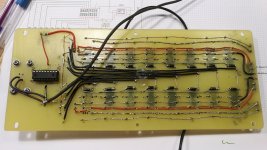
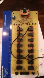
Well, photos, if you can get anything out of the mess but anyway; with this set up I have no ground problem and the pre amp is sounding wonderful and volume is regulated via an ordinary 10K pot.


Problem is when I want to connect the following buggers, a volume control from Jims Audio with rectifyer and regulation onboard, and then the source selector (to which I steal 12 volt from the volume control since it is only the relays using the 12 volts and current need is limited). I get a major ground loop and the transformer/transformers are sounding more than the music and it is just generally annoying to hear.


I can not see the problem since it should be to just follow the +/- and ground in and out since I am still connecting "within the circuit" but Oh NO, so easy it is not.
Then yesterday, ZenMod advised me to rectify the 15 VAC ouside the board and to feed the DC direct to the board (AC/gnd in the picture) since I suspect that the ground was not at 0 V since I was using a transformer with 15 - 0 volt instead of a center tapped 15 -0 -15 volt, which should be just fine so in comes a;


But NOOO! It doesn't change anything, the big humming bird is still nesting in my volume control, so what do I do, anyone?? Can it have anything to do with the fact that the volume control and the source switch are mounted on a steel plate so it is that one that has to be grounded....?? But on the other hand, I have nothing else connected to main ground at this set up so everything is just on wood boards exept for this steel plate that is...
If I don't get it right I will maybe choose a TKD pot but since I now have the real deal I would really get it running correctly.
When I am to it I just want to show the CD I am using to test this pre amp with, a Cambridge D500SE with a little twist. The original is OK but this is way better and still, the worst CD I have since I have one home built Playstation 1 and one Shiga in pipeline (recieved new laser heads today so tonight it is playing again).
I left my Cambridge to a friend who made some tweaks on it and this is what I got in my hands after some time in his hands.

- Home
- Amplifiers
- Pass Labs
- Pass Aleph P 1.7 preamp builders thread