PCB power supply.
Want to buy PCB for power supply.
Tried http://www.kk-pcb.com/index.html
Do not reply to e-mail
Anyone here who can help?
Want to buy PCB for power supply.
Tried http://www.kk-pcb.com/index.html
Do not reply to e-mail
Anyone here who can help?
Anybody have experience with purchases from
http://www.kk-pcb.com/index.html
KRISTIJAN KLJUCARIC
Payment for PCB sent on 27 September 2016
No goods received no reply to e-mail
http://www.kk-pcb.com/index.html
KRISTIJAN KLJUCARIC
Payment for PCB sent on 27 September 2016
No goods received no reply to e-mail
Attenuator?
Have come so far that I start thinking..... in putting things together cause I can, but then there is the matter of attenuator.
Yes, I could wait a little longer and get correct things from Dantimax but this was not the right month so then I have to wait for Christmas or even January.
Question is, have anyone here experience of the cheap attenuators from China?
Is is worth putting €40-€60 for a attenuator with "Dale" resistors or should I get one without resistors and build myself? Is the mechanical quality such that it is worth it or should I get something already built on Ebay or maybe even a Alps pot???
I want to hear my P1.7 now, that is why I don't want to wait any longer!
On the other hand, then I have a project for next year also, to rebuild it with correct selectors, relay attenuator and control board.
If you don't have work, then you have to create work!!
Have come so far that I start thinking..... in putting things together cause I can, but then there is the matter of attenuator.
Yes, I could wait a little longer and get correct things from Dantimax but this was not the right month
so then I have to wait for Christmas or even January.Question is, have anyone here experience of the cheap attenuators from China?
Is is worth putting €40-€60 for a attenuator with "Dale" resistors or should I get one without resistors and build myself? Is the mechanical quality such that it is worth it or should I get something already built on Ebay or maybe even a Alps pot???
I want to hear my P1.7 now, that is why I don't want to wait any longer!
On the other hand, then I have a project for next year also, to rebuild it with correct selectors, relay attenuator and control board.
If you don't have work, then you have to create work!!
I want to hear my P1.7 now, that is why I don't want to wait any longer!
On the other hand, then I have a project for next year also, to rebuild it with correct selectors, relay attenuator and control board.
If you don't have work, then you have to create work!!
I would buy 2 1k stereo pots for about € 3 to € 5 each. That way you can listen to you AP1.7 and take your time deciding what to build.
Later you can test if a resistor based attenuator is worth your while as follows:
1. Find a comfortabel SPL with a nice piece of music
2. Measure the resistance of the pot at that setting
3. Make up an attenuator from fixed resistors using the resistance measured in 2
4. Replace the pot by the discrete resistors
5. Listen and make up your mind!
PS Gerd just beat me to it!. Hi Gerd
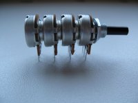
I will do a test with 2.2k pot. 4 gang at the output.
Just curious where you found this pot? I don't think I've seen one with
resistance that low.
Thanks,
Dennis
It was special made by company Omega limited.
They were not too happy for small orders.
Omeg Products
They were not too happy for small orders.
Omeg Products
A Dutch surplus webshop has different pots in stock, down to 1k.
https://www.eoo-bv.nl/357-potmeter-stereo-lin
https://www.eoo-bv.nl/358-potmeter-stereo-log
https://www.eoo-bv.nl/357-potmeter-stereo-lin
https://www.eoo-bv.nl/358-potmeter-stereo-log
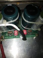
When i got home last Friday, i noticed that my Aleph P1.7 would not turn on. It was completly dead. It had been in standby mode for some days. But even the standby led was dead. The 1.6A fuse on the back panel was gone to the next life.
After some time, i noticed that the transformer on the standby PSU bulked. I checked the windings and sure, the primaries was burned up. No contact what so ever. the 3VA transformer from Dantimax was not able to support the input2, control2 and rel.vol3 Boards for to long. well, it took 9 years for it to fail. But that chould never happend.
i swapped it out for a 50VA transformer that i had. And the pre amp is once again up and running
I have built dual mono p 1.7. It plays ok and scope measurement also ok.
Supply voltage is around 61v. Why i get different voltage drops on 9610 mos fet. On one chanel is about 32v dc after 9610 on both sides and another channel 35.6V after both fets. I use bc560 instead ztx. On 32v pcb i have 2 same bc560 and on 35.6v board i have 2 bc560 from different producer. What can be cause of that imbalance?
Thank you.
I have built dual mono p 1.7. It plays ok and scope measurement also ok.
Supply voltage is around 61v. Why i get different voltage drops on 9610 mos fet. On one chanel is about 32v dc after 9610 on both sides and another channel 35.6V after both fets. I use bc560 instead ztx. On 32v pcb i have 2 same bc560 and on 35.6v board i have 2 bc560 from different producer. What can be cause of that imbalance?
Thank you.
The Circuit works by having 2 current sources of nominally 30 and 20ma. The difference current of 10ma flows through the grounded output resistors which are roughly 3.2k. So you get 32 volts for a DC output level. When I built my P1.7 I had a similar problem. Check the currents by measuring the voltage drops across the 33 and 22ohm resistors. This will tell you where the 2 sides differ. In my case I paralleled resistors to balance things out and get the DC output voltage where I wanted it.
Transformer problem??
I have started putting things together so that I will have a nice pre amp but today when I should put the transformers to their first test I experienced something strange.
Ok, I have two separate transformers for the Aleph P1.7 boards and those seem to work just fine leaving me with 63.2 and 63.4 Volt respectively. So far so good!
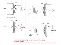
I also have a Dantrafo 2020112 that is supposed to leave me 2 x 15 Volt on the secondary to run the relays on both the Aleph P1.7 and signal board and volume control. It is built with a primary side consisting of 2 x 115 Volt that I understand should be hooked up as the picture is showing.

Here is the problem, when I connect it the fuse blows with a nice little flash, phuff!
I checked all cables and they are correct, and when I check for continuity from upper blue cable to lower blue cable in the picture I should receive a signal but it is dead quite, no sound not even a bip.
I think that my primary side is gone bye bye! Am I right?
I have started putting things together so that I will have a nice pre amp but today when I should put the transformers to their first test I experienced something strange.
Ok, I have two separate transformers for the Aleph P1.7 boards and those seem to work just fine leaving me with 63.2 and 63.4 Volt respectively. So far so good!
I also have a Dantrafo 2020112 that is supposed to leave me 2 x 15 Volt on the secondary to run the relays on both the Aleph P1.7 and signal board and volume control. It is built with a primary side consisting of 2 x 115 Volt that I understand should be hooked up as the picture is showing.
Here is the problem, when I connect it the fuse blows with a nice little flash, phuff!
I checked all cables and they are correct, and when I check for continuity from upper blue cable to lower blue cable in the picture I should receive a signal but it is dead quite, no sound not even a bip.
I think that my primary side is gone bye bye! Am I right?
I checked all cables and they are correct, and when I check for continuity from upper blue cable to lower blue cable in the picture I should receive a signal but it is dead quite, no sound not even a bip.
I think that my primary side is gone bye bye! Am I right?
It turns out that Dantrafo don't connect their trafo the way you generally do but connect incoming AC to 1 and 6 and you put jumper on 5 to 10. Apperantly the bugger is sensitive to directions so I will check later this evening if it still is alive otherwise I have to get a new one on monday.
- Home
- Amplifiers
- Pass Labs
- Pass Aleph P 1.7 preamp builders thread