Forget multipliers for this. You think too deep, both concept and implementation.
Lets keep at the conceptual level. Can we use a controlled current instead of a controlled impedance to do level control for these oscillators. All the rest is routine circuit design.
But first the concept.
Jan
Lets keep at the conceptual level. Can we use a controlled current instead of a controlled impedance to do level control for these oscillators. All the rest is routine circuit design.
But first the concept.
Jan
I recently remembered an AGC circuit from a very high performance military short wave receiver. It had some other requirements like exact 50 Ohm input impedance to keep a ring mixer happy, which was taken care of with some noiseless transformer feedback in Norton style. The whole thing looks somewhat like a differential amplifier plus some transformer ado at first sight, but it is not.
The core itself is really simple. It is like 2 cascode stages in parallel; the signal is fed into the emitters from a high impedance. One of the cascode stages develops the output voltage across a resistor, the other feeds a short circuit. For high gain, the output cascode stage gets all the current, for less gain, some of the signal current is diverted to the short circuited cascode. That ratio can easily be adjusted via the base potentials.
No inherent nonlinearity or compression. Part of the signal current is simply diverted into nirvana. Noise penalty of a common base stage? With enough current: nothing. Same for distortion: current rulez.
I want to try that in a Driscoll crystal oscillator.
Gerhard
Last edited:
I recently remembered an AGC circuit from a very high performance military short wave receiver. It had some other requirements like exact 50 Ohm input impedance to keep a ring mixer happy, which was taken care of with some noiseless transformer feedback in Norton style. The whole thing looks somewhat like a differential amplifier plus some transformer ado at first sight, but it is not.
The core itself is really simple. It is like 2 cascode stages in parallel; the signal is fed into the emitters from a high impedance. One of the cascode stages develops the output voltage across a resistor, the other feeds a short circuit. For high gain, the output cascode stage gets all the current, for less gain, some of the signal current is diverted to the short circuited cascode. That ratio can easily be adjusted via the base potentials.
No inherent nonlinearity or compression. Part of the signal current is simply diverted into nirvana. Noise penalty of a common base stage? With enough current: nothing. Same for distortion: current rulez.
I want to try that in a Driscoll crystal oscillator.
Gerhard
If I am not mistaken in understanding the circuit you describe, it is in the translinear family of gain control circuits. As I said, those tend to have a noise/distortion tradeoff that is not as good as other approaches. Translinear circuits can approach very good linearity if they are implemented with ideal transistors. Sadly, in reality, ohmic elements, such as base resistance and emitter resistance, usually introduce nonlinearity.
Cheers,
Bob
Sadly, in reality, ohmic elements, such as base resistance and emitter resistance, usually introduce nonlinearity.
Bob there's a lot of now public domain IP in Dave Blackmer's and maybe our patents on compensating for these effects.
[special=]%[/special]
I think one would insert a DC bias current into the top node of the controlled current source. Like if you used a FET you'd insert a DC bias into D. Like a resistor to a clean DC supply point. Would that work with these oscillators? You could even couple the controlled cs to the control node capacitively.
BTW the larger question is can we use a controlled current as control element. The solutions with FET or lamp or CDS cell all conceptually rely on a controlled resistance. I propose a controlled current which can be made as linear as you care.
Edit the linearity of concern is the voltage dependence of the controlled element I believe.
Jan
Absolutely you can use a controlled sinusoidal current. That you can put directly into the inverting node of the inverting amplifier of an SVO.
The multipliers in the Boonton are current output. I believed the same for the Shibasoku oscillators. After all it's a current at the inverting node of an op amp
The thing with an SVF is that the amount damping is frequency dependent. You can see this by looking at the design equations for an SVF. One really needs a variable damping for a multi frequency SVO. The pos FB can be fixed and then vary an inverted copy of the FB signal in the ring. Can you do this with the an IL300 and get enough authority out of it?
Or as Bob pointed out, use a secondary control for out of range control.
I think I posed a while back a simple jfet circuit that can do this triggered by a set threshold level off the oscillator.
Last edited:
I think in both the Shibasoku and the Boonton the currents are converted into voltages for the opamps. Bipolar current sources are not so easy. The Boonton's AGC uses the same time constants for 10 Hz to 140 KHz on its SVO and seems to work pretty well. I need to get back to tweaking it.
The Shibasoku is more conventional. Attached are LTSpice sims of the Shibasoku oscillators. I'm embarrassed to admit I have forgotten who passed them to me. It shows how they coupled the multiplier to the system in a full 4 quadrant mode. The Shibasoku is good for -130 dB or better for its harmonics.
The Shibasoku is more conventional. Attached are LTSpice sims of the Shibasoku oscillators. I'm embarrassed to admit I have forgotten who passed them to me. It shows how they coupled the multiplier to the system in a full 4 quadrant mode. The Shibasoku is good for -130 dB or better for its harmonics.
Attachments
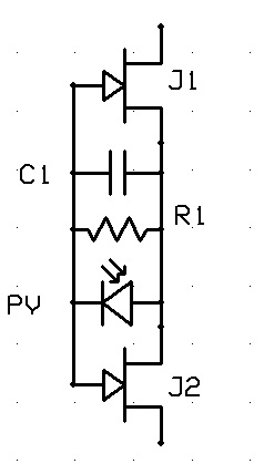
Anyone ever try this? J1 and J2 form a FET with center tapped channel...
Hi Scott
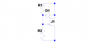
How about this? Still cancels the variable drain-source potential but saves a FET, so I can use the matched halves of a dual JFET in a classic balanced circuit that should cancel practically all residual distortion.
I have also removed the capacitor to eliminate a pole, should make it easier to optimize the leveler control loop dynamics.
Best wishes
David
Attachments
Last edited:
Hi Scott
How about this? Still cancels the variable drain-source potential but saves a FET, so I can use the matched halves of a dual JFET in a classic balanced circuit that should cancel practically all residual distortion.
I have also removed the capacitor to eliminate a pole, should make it easier to optimize the leveler control loop dynamics.
Best wishes
David
Should work, as long as the diode stays a current source. It might need to go gate to source for that.
Last edited:
The Shibasoku is more conventional. Attached are LTSpice sims of the Shibasoku oscillators...
Well timed, thanks, I had finally realized that the simplest solution was a multiplier and the AG16 in particular has a very simple main loop and excellent performance.
A pity that the nice multipliers, while simple, are not cheap. Bob still has a point that JFETs are a cost effective solution.
What do you think of my JFET idea in the previous post?
Best wishes
David
..as the diode stays a current source...
In practice I plan to use two diodes, one to provide an offset so that the inherently uni-polar diodes produce a bi-polar output.
Then I can balance the whole circuit and have complete distortion cancellation, to the limit of the dual JFET match at least.
Best wishes
David
A pity that the nice multipliers, while simple, are not cheap.
Blackmer VCA's are as good as classic multiplier cores without the fancy calibrated voltage in/out interface. I certainly could send some classic multipliers (don't know what I have in the junk bin).
Last edited:
...I certainly could send some classic multipliers (don't know what I have in the junk bin).
That is a remarkably kind offer, thank you very much but I won't take it up yet.
I want to do a circuit that will appeal to DIY participants to reproduce, but top-specification AD734B is over $100 Australian and even the lower spec. "A" bin is at least $60.
The Blackmer VCAs are impressive but only two quadrant, that loses some of the simplicity of a four quadrant multiplier.
So I will see if I can come up with a satisfactory JFET solution a bit cheaper, I finally have an outline that I am happy with.
AD will still sell some parts, I use three AD797s for the oscillator core.
")
And part of the fun is to try to demonstrate the use of theory to produce a cost effective solution
On that idea, I plan use two-pole compensation for the 797s, it makes sense to me and JCX did some simulations that support the idea, any recommendations?
Best wishes
David
A pity that the nice multipliers, while simple, are not cheap. Bob still has a point that JFETs are a cost effective solution.
Best wishes
David
The AD633 can be had for $6 in singles. The Jfet duals can be that expensive. The Motorola part in the AG16 is obsolete. The Boonton has switched to the AD633 on the current version from the long obsolete RC4200. The KH4402 uses an AD633. The AD633 is voltage so its easier to use as well. I don't know if it will limit performance vs. a Jfet.
The circuit in the AG16 is not the easiest to follow. I hope you got a good sense for it.
Just to keep things moving I have attached the analog circuitry of the Racal 9023 low distortion oscillator. It's performance is quite good. The UI is annoying but its fully GPIB so I think the UI is an afterthought. In any case you can see the 4 quadrant multiplier executed with the CA3096 and the CA3280 OTA's. The CA3096 is obsolete but Intersil has an HFA3096 with 8 GHz transistors (and a max voltage of 8V so NOT a substitute).
Attachments
The AD633 can be had for $6...
I did say the "nice" multipliers
I plan a sweepable oscillator so I need reasonable control authority to deal with mismatch in the potentiometer tracks.
That means I can't decouple the multiplier as heavily as the fixed frequency units, which makes the multiplier more critical, hence my preference for the lower distortion AD734 over the admittedly well priced AD633 .
Unfortunately, as I wrote in the previous post, the baseline AD734 is >$60 in Australia.
For ~$6 I think I can do better with a dual JFET.
I don't know if it will limit performance vs. a Jfet.
Samuel alerted me to the noise issues of the IC multipliers and Bob has also mentioned it.
My very approximate estimates have it just acceptable when decoupled, but there's not much to spare.
A synchronous FFT can "sweep it under the carpet" but better if it's not there at all I think.
Best wishes
David
Is "synchronous" the pedantically correct term for when the noise is correctly reduced by multiple samples?
Last edited:
The KH4402 uses the AD633 for a 1 Hz to 100 KHz oscillator with -130 dB range distortion. Richard Marsh has measured his and posted the results. The KH4402 does switch the time constant in the AGC for different ranges. The Boonton is 10 Hz to 140 KHz without switching time constants but has a much more involved SH +TH level sensor.
Looking at the specs on one path (Y) the AD633 is the same .1% as the AD734. The AD734 shines at 10 MHz. That's usually a different application.
If you use reasonably accurate parts (1%) for the tuning you should not need an enormous dynamic range on the loop.
Looking at the specs on one path (Y) the AD633 is the same .1% as the AD734. The AD734 shines at 10 MHz. That's usually a different application.
If you use reasonably accurate parts (1%) for the tuning you should not need an enormous dynamic range on the loop.
... the specs on one path (Y) the AD633 is the same .1% as the AD734...
The specs of the 734 and 633 are not reported in exactly the same format and I initially did not notice the superiority of the 734 either.
But under comparable conditions the Y path 633 is 0.1% versus the 734 at 0.025%.
Over full 4 quadrants the 633 is 1% versus the 734 at 0.1%.
Feedthru of the 633 is 60 dB typical versus 734 at 85 dB typical.
And so on, except noise is practically identical.
One possibility would be to have the 633 as the baseline and the 734 as a performance enhancement option, I think they are compatible.
Best wishes
David
They are broadly compatible in terms of levels and function but not pin-for-pin replacement.
Maybe a clever layout could fix this but it's the sort of complication I wanted to avoid.
Last edited:
The real question is if the differences would affect the overall performance. Scott may be able to help. My experience suggests that other aspects may be a limitation before the multiplier. On the Shibasoku I tried 5 samples of the Motorola and saw no changes in the distortion. I think you could do them side by side successfully.
The AD797 is not real easy to use. The issues with input impedances and optimum noise need to be examined. On several occasions the LME49710 was quieter with no distortion penalty.
The AD797 is not real easy to use. The issues with input impedances and optimum noise need to be examined. On several occasions the LME49710 was quieter with no distortion penalty.
...The AD797 is not real easy to use.
Indeed, but it is unique in the ability to optimize the feedback via the use of the "distortion cancellation" pin.
Part of the idea is a demonstration of feedback theory to produce better practical results.
The issues with input impedances and optimum noise need to be examined...
Yes, I have already had a think about this and the AD797 is nice here too because it has excellent ability to drive the lowish impedances needed to keep the noise down.
A composite amplifier could presumably be used but, as always, I want a simple solution and the AD797 looks to do the job by itself very well.
Hence my interest for any comments by Scott.
Best wishes
David
In practice I plan to use two diodes, one to provide an offset so that the inherently uni-polar diodes produce a bi-polar output.
Then I can balance the whole circuit and have complete distortion cancellation, to the limit of the dual JFET match at least.
Best wishes
David
Hi Dave,
Its still a bit early in the morning and I have not yet finished my second cup of coffee, so forgive me if I am confused or get this wrong. With respect to the center-tapped FET approach that you and Scott have been talking about, it is a clever way to achieve the 1/2 signal feedback to the gate(s) that we all use to reduce the FET's distortion contribution. We also know that, in practice, the 1/2 feedback does not perfectly eliminate the JFETs distortion contribution. I do not think that the center tapped FET approach reduces or cancels any more distortion than the conventional approach that uses a single shunt JFET where 1/2 of the drain-source signal voltage is fed back to the gate.
As long as the FET-based variable resistance FET arrangement has any signal across it (which it must, in order to act as a variable resistance-attenuator of some sort), the natural tendency of the FETs drain-source resistance to increase as the drain source signal voltage increases in magnitude will remain, and its effect can only be reduced by feeding back 1/2 the signal to the gate (or a value that may be slightly different than the theoretical 1/2 amount in my experience). I don't think the "balanced" or "push-pull" or "complementary" appearance of the center-tapped FET approach does anything more in practice than the classical 1/2 feedback approach. It certainly does not seem to cancel or otherwise reduce the net amount of signal appearing from drain to source on the FETs.
I have many times tried to come up with a circuit that is fundamentally better by using a dual-matched JFET to do this, perhaps in some way with one creating a replica of the distortion created by the other, but have not been successful in ending up with anything better than a well-deigned classic approach where one JFET is used with the 1/2 feedback approach. Maybe I am missing something.
Cheers,
Bob
Hence my interest for any comments by Scott.
Best wishes
David
I have not played with these compensation tricks for years, I'm sure jcx could get you started down the right path. First box I grabbed had some DIP 734's so keep it in mind. It's amazing how much stuff was tossed due to the lead free initiative. I missed out on dumpsters full of demo cards and reference designs.
Last edited:
- Home
- Design & Build
- Equipment & Tools
- Low-distortion Audio-range Oscillator