Not necessarily. A servo pot can have essentially no backlash and 1,000,000 cycle life or more...
Yes, these are fine for, say, an encoder on a robotic positioner or some such.
But for an oscillator control the wiper would be at some point on the track and then fret back and forth over that spot in response to tiny variations in the amplitude.
The backlash I had in mind was not from the pot itself but the motor drive, typically with a mechanical reduction 'box.
I have considered it as a low distortion, non volatile coarse adjustment, perhaps with electronic fine trim but it seems unnecessarily complicated and expensive.
Maybe that's perfect for the "boutique audiophile" market but not for a serious instrument.
I like to consider "out of the box" solutions but I think there's a reason this one isn't used.
The fact that some decent oscillators use each of the other techniques implies there isn't a clear winner.
Best wishes
David
Cross posted with Scott, I rest my case.
Last edited:
I have also read that the opto-couplers don't match that closely, so distortion cancellation may be more limited than one would like. Anyone have data on this?
But they do make it simpler.
Best wishes
David
David you may want to take a look at the IL300 matched optocoupler (there's also a 2nd source from Avago, now Broadcom, iirc HCNR200). You can use these in a feedback arrangement which makes the (open loop) forward transfer better than 0.1% linear.
I have used these as high-voltage isolators and they are linear enough for high-quality audio.
Jan
David you may want to take a look at the IL300 matched optocoupler...
Hi Jan
When I commented on the poor match of opto-couplers it was in the specific context of the Cadmium Sulfide photo-resistive units like the NSL32.
Photo-diode couplers are yet another option and it's hard to study them all carefully.
Scott showed a possible use of this a few days back and I did look at the IL300 datasheet briefly then.
Do you have an idea how best to use it?
My idea is for a leveler based on a dual JFET used in a balanced divider.
It should be possible to trim for zero output at nominal operation point so the distortion should cancel almost completely.
Maybe I don't need to cancel the variable Drain-Source potential for each FET individually, simpler not to but it feels safer to do so.
How would you use the IL300 to drive JFETs?
Best wishes
David
You must be thinking of the original Vactrol (there are several models) originally made by Vactec. This is not the only LED-LDR device made (originally using an incandescent or even neon lamp before LEDs became common), and certainly not the only maker of light-dependent resistors, but as you suggest, the LDR or Cds photocell is notoriously inconsistent as far as resistance generated for a certain amount of light. The Vactrol models were substantially less inconsistent, and so became popular in semi-critical applications (the big one is in audio dynamic range compression for recording studios). Also, the company that made them did get bought and sold, and changed names a few times, much like most other electronics manufacturing firms.Yes, I checked too.
But Cadmium is not RoHS compliant and the CdS photocell production has been passed from company to company, now Luna, previously Silonex, previously Vishay was it? then National I think?
It was about a year ago that the official Vactrols were discontinued, obviously due to equipment using them not being able to be sold in Europe because of the latest ROHS regulations. The market prices for certain Vactrol models have skyrocketed in the last year as a result.
But similar devices are still being made and sold by others. Here's a longish thread on the situation:
https://groupdiy.com/index.php?topic=63974.0
You must [mean]...Vactrol (there are several models)
No, the post to which I responded specifically mentioned the NSL 32, made by Luna, previously etc. etc. (Advanced Photonics should have been in the list too).
The NSL 32SR3 variety is said to be the lowest distortion photo-resistive unit and has been the unit of choice for oscillators.
But your thread confirms my concerns about availability of photo-resistive units.
The IL300 photo-diode looks like it could work well as a FET driver.
Not quite as simple as the direct use of a photo-variable resistor in a divider but not bad and should be better matched.
The IL300 can work in different modes, photovoltaic or photoconductive, anyone have advice on the best way to use this in conjunction with the distortion reduction technique for FETs?
Best wishes
David
How would you use the IL300 to drive JFETs?
Best wishes
David
Hello David,
I thought the output diode could be used directly, as an impedance that varies for the signal depending on the primary drive. Replace the FET, not drive it.
The advantage would be that you have a linear relationship between the input drive (I think what Bob calls the error voltage) and the output diode ac impedance.
Biasing aside, on the input side you have an opamp driving the LED with the input side diode in the feedback loop. So the input side signal current varies linearly with the error voltage that drives the opamp circuit, and by virtue of the excellent matching, the same signal current flows in the output diode. So you have an 'output side impedance' linearly related to the error voltage. And unlike the FET, that impedance does not change with signal amplitude so no distortion from that part.
Jan
Last edited:
I thought the output diode could be used directly, as an impedance that varies for the signal depending on the primary drive. Replace the FET, not drive it. The advantage would be that you have a linear relationship between the input drive (I think what Bob calls the error voltage) and the output diode ac impedance.
Modest nonlinearity with respect to the control voltage is no issue (or, if properly designed, in fact advantageous to speed up settling), as it is reduced by the loop gain of the leveling loop.
Critical is the nonlinearity with respect to the audio/oscillator signal. A diode basically performs rectification, so is rather poor in this respect.
Whathever approach we choose for the multiplier element, in the end it's a trade-off between power and noise/distortion performance. We can easily derive arbitrarily good performance by paralleling enough multipliers. Paralleling multipliers reduces their noise contribution, which allows lower operating levels, which in turn reduces distortion (for typical distortion behavior).
The translinear BJT multiplier is particularly suitable for this approach, because increasing the quiescent current of the core results in a very similar scaling effect without increasing the complexity.
Samuel
...the output diode could be used directly, as an impedance that varies...
Jan, perhaps I don't understand photo-diodes or miss your point, but I don't see that this will work well.
The feedback can not linearize the dynamic diode resistance of the output diode so I expect it would be far from linear for any more than tens of millivolts applied across it.
The JFETs that are optimized as VCRs should be linear over at least 10 times that.
I noticed that Scott's circuit used the photo-diode to drive a JFET and perhaps this has biased me but it makes sense to me.
Best wishes
David
Damn, last time cross posted with Scott, this time with Samuel.
I need to think and type faster.
Last edited:
Jan, perhaps I don't understand photo-diodes or miss your point, but I don't see that this will work well.
The feedback can not linearize the dynamic diode resistance of the output diode so I expect it would be far from linear for any more than tens of millivolts applied across it.
The JFETs that are optimized as VCRs should be linear over at least 10 times that.
I noticed that Scott's circuit used the photo-diode to drive a JFET and perhaps this has biased me but it makes sense to me.
Best wishes
David
Damn, last time cross posted with Scott, this time with Samuel.
I need to think and type faster.
(Also @ Samuel) Actually, the output diode will be used in reverse mode, and the drive from the coupler will cause a photodiode reverse current linearly related to the driving error voltage. So it is just like a linearly controlled impedance.
This reverse current is basically independent of the actual signal voltage across it which is the issue with a FET as I understand.
Of course proper biasing is necessary. In one of my applications I bias the diode with a reverse DC current of 100uA and then modulate it with a linear signal into the driving opamp at 10 or 20uA RMS. Pretty much perfectly linear and no output signal dependence.
In an amplifier you'd put an R in series with the output diode to pick off the signal voltage but in this app the reverse diode can stand on itself as voltage controlled impedance.
Jan
Last edited:
...Actually, the output diode will be used in reverse mode, and the drive from the coupler will cause a photodiode reverse current...
I see what you mean but my feel is that it won't work well, so I am hesitant.
That's part of the reason I typed my reply so slowly that Samuel posted in the meantime.
However, if you have tested this then maybe I just need to rethink it.
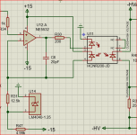
The conceptual sketch you sent doesn't look like LTspice, have you Spiced it and could you attach the photo-coupler model so we can compare simulations?
Best wishes
David
I don't see how that would work either. You described it by saying, "the drive from the coupler will cause a photodiode reverse current linearly related to the driving error voltage." It sounds like you are saying it acts as a current source. If so, that is very different from a photo-resistor that acts as a variable resistor that is part of a voltage divider. Not clear to me how to use a current source to make a ultra-low distortion signal attenuator that would accomplish the same purpose. Maybe you could describe the proposed circuit operation a little more make it more obvious.
Think of it as a variable impedance - FET, CDS cell, reverse biased photo diode, same concept.
Being a voltage to current converter you probably need to add a sample of the signal to the error voltage that drives it. In the circuit fragment I posted, at the opamp non-inverting input. The output reverse biased diode would form the variable impedance, without the series resistor, but with a DC bias arrangement.
The main advantage as I would see it is that unlike the FET for instance, the impedance does not vary with the signal voltage across it.
There is a Spice model in the datasheet of the HCNR200 from Avago, now Broadcom. And my Spice sim is indeed not LTspice - I actually paid for mine")
Jan
Being a voltage to current converter you probably need to add a sample of the signal to the error voltage that drives it. In the circuit fragment I posted, at the opamp non-inverting input. The output reverse biased diode would form the variable impedance, without the series resistor, but with a DC bias arrangement.
The main advantage as I would see it is that unlike the FET for instance, the impedance does not vary with the signal voltage across it.
There is a Spice model in the datasheet of the HCNR200 from Avago, now Broadcom. And my Spice sim is indeed not LTspice - I actually paid for mine
Jan
Jan,
Okay, thank you. So, if I understand correctly, you suggest to add the oscillator signal with the error voltage and run both of them through the optocoupler in order to change the oscillator signal level. If so, then it would seem that the optocoupler would be acting as some type of multiplier. So far in trying to understand, that makes me wonder if the distortion of the optocoupler circuit has been measured and found to be extremely low? I wonder because it would seem that the large signal transfer function of the optocoupler circuit would have to be nonlinear for it to act as a multiplier. In that case it would only be approximately linear for small signals. Or maybe I am still not correctly understanding how the circuit would operate?
Okay, thank you. So, if I understand correctly, you suggest to add the oscillator signal with the error voltage and run both of them through the optocoupler in order to change the oscillator signal level. If so, then it would seem that the optocoupler would be acting as some type of multiplier. So far in trying to understand, that makes me wonder if the distortion of the optocoupler circuit has been measured and found to be extremely low? I wonder because it would seem that the large signal transfer function of the optocoupler circuit would have to be nonlinear for it to act as a multiplier. In that case it would only be approximately linear for small signals. Or maybe I am still not correctly understanding how the circuit would operate?
OK, forget the term 'optocoupler' because I sense it has a predetermined connotation that turns a lot of people off. Just think of a black box that has an input and an output, and a very linear transfer function Iout = K. Vin. Just like a FET would have a transfer function Id = K. Vgs. You could even put a label on the black box 'FET special # 9' ;-)
I propose to replace the contents of the box with something that might be better at what it is supposed to do.
What I am not yet clear myself is this. The FET is used in its saturation region where Id = K.Vgs is no really true, if I understand correctly. Rather, in the saturation region it would be Rd = K.Vgs. Right?
So now I have my optical circuit which has Iout = K. Vin. As if you use the FET in the pentode region. Being a voltage controlled current source rather than a voltage controlled resistor. My question is then would it be possible to use a voltage controlled current source rather than a voltage controlled resistor as the level control element in your oscillator? Because if you can, one source of distortion could be eliminated, namely that the FET Rd is non-linear with regards to the voltage across it, while the controlled current source does not show this non-linearity.
So, lets concentrate on the conceptual level rather than get bogged down in circuit details. What do you say?
Jan
[special=]%[/special]
I think one would insert a DC bias current into the top node of the controlled current source. Like if you used a FET you'd insert a DC bias into D. Like a resistor to a clean DC supply point. Would that work with these oscillators? You could even couple the controlled cs to the control node capacitively.
BTW the larger question is can we use a controlled current as control element. The solutions with FET or lamp or CDS cell all conceptually rely on a controlled resistance. I propose a controlled current which can be made as linear as you care.
Edit the linearity of concern is the voltage dependence of the controlled element I believe.
Jan
Jan would you describes this as being analogous to a telephone system. In telco there is a dc current loop, A transformer winding in series in the loop modulates the dc current.
This sort of idea?
How would you remove the dc part of the signal?
I think one would insert a DC bias current into the top node of the controlled current source. Like if you used a FET you'd insert a DC bias into D. Like a resistor to a clean DC supply point. Would that work with these oscillators? You could even couple the controlled cs to the control node capacitively.
BTW the larger question is can we use a controlled current as control element. The solutions with FET or lamp or CDS cell all conceptually rely on a controlled resistance. I propose a controlled current which can be made as linear as you care.
Edit the linearity of concern is the voltage dependence of the controlled element I believe.
Jan
Last edited:
Think of it as a variable impedance - FET, CDS cell, reverse biased photo diode, same concept
While a FET and a CdS photo-coupler are both variable impedances I don't think a reverse biased photo-diode is useful for this role.
My question is then would it be possible to use a ... controlled current source rather than a ... controlled resistor as the level control element in your oscillator?
As far as I can see, a current controlled level element would simply be a multiplier - and if I had a suitable multiplier there would be no need to use an opto-isolator to drive it.
Also doesn't this contradict the first quote?
Best wishes
David
I seem to have reinvented Samuel's multiplier solution, so probably worth a look at his implementation to see how much simplification could be done without too much lose of performance.
Last edited:
JFETs are hard to beat
I honestly believe that a properly-designed JFET agc element is very hard to beat, both in terms of distortion and noise that it adds to the loop. The S/N of the agc element is very important to comprehensively good oscillator performance. There is an obvious tradeoff. You can make the distortion of the JFET agc element arbitrarily small if you operate it at a very low signal level, but this hurts the noise of the oscillator. It is also true that operating the agc circuit with very little "authority" (control range) can reduce its distortion contribution. This is more easily accomplished with fixed frequency oscillators where the need for variation in agc is minimal, especially for a 1kHz oscillator. I am talking about fully variable frequency oscillators. The rubber on these really meets the road when operating at very low frequencies (including long settling time) and high frequencies, like 20kHz.
I consider my agc loop in my THD analyzer to be one that is "properly designed" and of relatively small complexity and expense, but I'm sure it can be improved. The 2N4091 is one of the best VCR JFETs I have found. It has a high princhoff voltage and low Rds_on.
In principle, if you want to get more complex, you can design an agc element that has smaller authority and whose control range can be augmented by a passive switched trim circuit that switches its trip level when the JFET agc portion is out of range.
Speed of response of the agc element can also be an important issue, and the JFET can be quite fast, as opposed to, say a lamp. Added control poles in the agc loop are problematic, especially if they move across different frequencies.
Most of my comments are made in the context of a state variable oscillator, but usually apply to other oscillator topologies as well.
As far as quality of agc element goes, someone should probably measure the distortion and noise contribution of different agc elements by themselves for a proper comparison. there may also be in-situ approaches to such a measurement as well.
Of course, if you really want to go crazy, as has been mentioned for I think multipliers, you can get the noise contribution down by maybe 6 dB if you parallel 4 such circuits. My experience in the past is that translinear circuits like multipliers and VCAs tend to be noisy compared to other approaches, but they have probably improved in more recent years.
Finally, in your designs, make absolutely certain that the agc element is the major contributor to distortion and noise before knocking yourself out on it. The major contributor may instead be the agc control circuit and ripple from it that remains after the filtering (or something else). Choosing lower-impedance tuning elements can also help reduce oscillator noise. Once again, make sure that the oscillator-proper elements are not the dominant contributors to distortion or noise (unlikely if good op amps are used).
Some idea of this can be gotten by drastically reducing the agc authority (e.g., increasing the resistance that typically injects the agc correction signal into the oscillator signal path, and using a 10-turn pot to adjust the circuit gain to get within the now-small range of the agc circuit. If this exercise does not substantially reduce distortion, the oscillator-proper may be dominating distortion or noise.
Cheers,
Bob
- Home
- Design & Build
- Equipment & Tools
- Low-distortion Audio-range Oscillator