... I have not yet finished my second cup of coffee...
Hi Bob
It's not your coffee! My post was poorly formatted because of the way the forum software handles pictures.
I repeated Scott's circuit in my post for convenient comparison with my circuit, but Scott's picture was in-line and came out more conspicuous than my own, which was an attachment.
So my point was kind of lost, made worse because quotes in response drop the attachments but include the inline.
So here are two attachments to clarify.
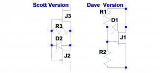
The first shows the difference between a simplified version of Scott's circuit and my circuit.
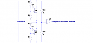
The main difference is that my version only uses one JFET, this lets me use the two halves of a dual JFET in a balanced circuit, as shown in the second attachment.
So I have the 1/2 Drain-Source cancellation on each side and then cancel any residual.
I pretty much concur with your comments, similar to what I had in mind when I came up with this idea, does it make sense?
Best wishes
David
I left out the drive circuit for the opto-diodes but it should be reasonably clear they are driven in opposition.
Attachments
Last edited:
David, why you wish to use the photocells for to drive the FETs? The optocoupler can produce very small current, and this may be the cause of the high impedance's problems. Also the DC offset will be injected in the signal loop.
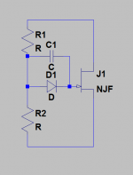
Balanced regulator idea is very good, but not new. Probably interesting working condition would be, when the both opposite FETs normally run in the possible maximum open mode (minimum drain-source voltage drop), and one of them goes to the little higher impedance if needed. One of the simplified implementations in the oscillator's inverter may looks that:

Victor.
Balanced regulator idea is very good, but not new. Probably interesting working condition would be, when the both opposite FETs normally run in the possible maximum open mode (minimum drain-source voltage drop), and one of them goes to the little higher impedance if needed. One of the simplified implementations in the oscillator's inverter may looks that:
Victor.
David, why you wish to use the photocells for to drive the FETs?...
Hi Victor, I only tried the photocells because it seemed a simple way to apply 1/2 drain source potential and then balance both FETs.
I realized it could be done with a few extra op-amps but I am not so experienced that I can draw circuits immediately.
So the JFET circuit was proposed for discussion first, I am not determined to use it.
I did think about the impedance issue, typical photo voltaic couplers can put out about 50 uA so the divider impedance would be around 10k to 100k, very approximately. That seems not too bad.
I did plan to run the FETs close to maximum conductance, just as you mentioned.
I even considered if it would be reasonable to run them symmetrically around zero, with forward bias on one FET junction but too small to have detectable conduction. But simpler without it I think.
Thanks for the comments, I use your circuit as a benchmark for simple but effective implementation.
Best wishes
David
In practice I plan to use two diodes, one to provide an offset so that the inherently uni-polar diodes produce a bi-polar output.
Then I can balance the whole circuit and have complete distortion cancellation, to the limit of the dual JFET match at least.
Best wishes
David
Can you? with single jFET, and 1/2v fb you really only reduce 2H. How to also reduce the stubborn 3H ??
THx-RNMarsh
Can you? with single jFET, and 1/2v fb you really only reduce 2H. How to also reduce the stubborn 3H ??
THx-RNMarsh
1/2 JFET gate feedback reduces 3H of the agc element.
Cheers,
Bob
1/2 JFET gate feedback reduces 3H of the agc element.
Cheers,
Bob
Up to a point, perfectly symmetrical the FET I/V through the origin has inherent 3rd's depending on the FET. I've tried to use a distortionless gain control (in the simple two op-amp circuit) and found it almost impossible to stabilize. Folks have had that problem with the LT "distortionless" oscillator also.
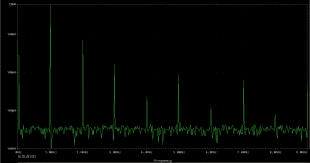
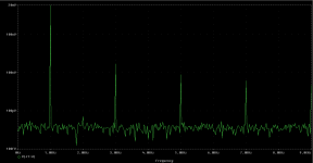
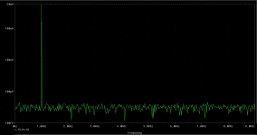
Here are the simulation results. 1kHz 20mV peak d-s voltage on every FET.
1) Without 1/2 d-s voltage on gate.
2) With 1/2 d-s voltage on gate.
3) Divider from the two identical FETs in the same condition.
1) Without 1/2 d-s voltage on gate.
2) With 1/2 d-s voltage on gate.
3) Divider from the two identical FETs in the same condition.
Attachments
Here are the simulation results. 1kHz 20mV peak d-s voltage on every FET.
1) Without 1/2 d-s voltage on gate.
2) With 1/2 d-s voltage on gate.
3) Divider from the two identical FETs in the same condition.
This shows what I just said. with the jfet, you cannot get both 2H and 3H to null. 2H can be nulled but 3h didn't go away for my tests.... mostly with the 339A design.
So, please refer me to the circuit for (3). Is this what you have done with your gen/ossc???
THx-RNMarsh
Last edited:
Can you?... How to also reduce the stubborn 3H ??
I use two FETs from a monolithic dual. Please check the circuit I posted in #6821.
From Victor's description this is what he has simulated in picture 3.
I did not even simulate that section, it's clear that distortion cancellation is mathematically ideal.
The limit will be set by how well the two JFETs match in reality, for a monolithic dual this should push that particular distortion another 40 dB or so below the level already possible with Victor's oscillator.
What will set the distortion limit in practice is unknown to me, probably have to build it and see.
I like LTSpice and the mathematical accuracy is extraordinary but accurate simulation at this level is problematic because non-ideal practicalities will dominate.
Best wishes
David
Last edited:
So, please refer me to the circuit for (3). Is this what you have done with your gen/ossc???
THx-RNMarsh
Unfortunately no. This is only result from the simulator. I thought about the balanced regulator, but I have no practical realization at this time. Many problems must be solved before this type of the regulator may take effect in practice. In my opinion, this regulator is reasonable when the oscillator harmonic levels can be dropped under -160db, and also can be properly measured. If the other parts of the oscillator can't produce so clean signal, and the measurement tool can't measure it, then no reason for to use. Will be step by step a long way, and maybe in future...
Victor.
1/2 JFET...
Cheers,
Bob
Bob, you haven't commented on my post #6821.
Did it clarify the situation and address your concerns?
Best wishes
David
Bob, you haven't commented on my post #6821.
Did it clarify the situation and address your concerns?
Best wishes
David
Hi David,
Sorry, I had a lot of distractions lately with doing a house move, so I have not been completely on my game lately.
I'm having some trouble understanding what the diode is for.
Also, I'm having trouble getting past the fact that the Rds on a JFET increases as Vds increases - in either polarity - since the JFET is nominally symmetrical, and any amount of Vds increases the depletion region and the pinch on the channel with any given amount of pinch that is already there due to the reverse bias on the gate. I don't see how creating a balanced arrangement cancels out any 3rd order harmonics that remain after the 1/2 gate feedback has done the best it can to reduce the thirds.
Finally, I would caution against anyone depending on simulation for the evaluation of JFET agc distortion, since the JFET model is generally over-simplified. One example of such oversimplification (although maybe not the relevant one here) is that JFETs have subthreshold conduction just like MOSFETs, and this is not covered in the model. Overall, I think the simpler models of the JFETs transition from the triode region to that saturation region leave a bit to be desired. So in this agc distortion department, I would tend to only trust actual distortion measurements of a real JFET agc element by itself.
Cheers,
Bob
Hi Bob, I hope the house move is smooth, don't worry if DIY has to take second priority.I had a lot of distractions lately
That's the photo-diode of the opto-coupler, used in photo-voltaic mode to bias the JFET....what the diode is for.
LTspice doesn't seem to have a photo-diode symbol and I haven't created one yet, just drew a line to represent the "photo" bit.
Best wishes
David
It's a classic Wheatstone, any variation in the impedance of the JFET is duplicated in both arms so the op-amp sees no input.I don't see how ...balance...cancels out any 3rd order harmonics that remain
Some third will presumably sneak in, as control is applied and balance is disturbed, but it can be made arbitrarily close to zero, subject to JFET match.
Me too, that's why I said "I like LTSpice and the mathematical accuracy is extraordinary but accurate simulation at this level is problematic because non-ideal practicalities will dominate." in #6829.I would tend to only trust actual distortion measurements of a real JFET
Last edited:
Here is a small rearrangement of the PV+Jfet idea. The PV diode doesn't need to supply any current. The cap across it may or may not be necessary (not sure how noise aspects would work in this).
It can be used as a variable resistor in any configuration since no element needs reference to ground. I would add a trimmer to optimize the divider for the specific Jfet operating point. The total R would be the max desired R in the location.
Driving an LED from a level detector should be straightforward however if you use an incandescent lamp you can dispense with level detection and any transients associated with it. If you can find a lamp with a vacuum and couple it to the PV cell optimally (good thermal isolation) you would be close to what you get with a vacuum thermocouple with the potential of improved flatness. Probably would not work that well but sounds impressive.
(I also one proposed a preamp powered from a 100W incandescent lamp coupled to a PV array for very high supply isolation. Too many years in Audiophilia lunacy.)
Attachments
... if you use an incandescent lamp you can dispense with level detection and any transients associated with it.
I build a low distortion thermistor stabilized oscillator, the amplitude bounce is wretched despite use of the most sensitive, vacuum insulated thermistor variety ever available.
An incandescent lamp is also a thermal system and I think there are theoretical reasons that any such control system will have similar problems.
So, previous experience has left me with a real aversion to the idea, I don't care how low the distortion is.
I believe I can achieve low distortion and nice control dynamics with FETs or multipliers.
..with a vacuum thermocouple with the potential of improved flatness.
Do you mean one of the vacuum thermistors like the r53?
If you look at the fine internal wires it does look like a thermocouple.
Best wishes
David
Last edited:
Could anybody here do me a favor and attach the latest circuit of the oscillator that is being discussed?
I don't have a full circuit yet.
The core idea is a state variable oscillator, this is almost standard except for use of 3 x AD797 with two pole compensation.
The detector is based on sum of squares of the sine and cosine, I currently plan to use an LM13700 as squarer and the circuit is from the application notes for this IC.
Level control is a dual JFET VCR11 from Linear Systems. In post #6821 there is a sketch of a balanced control that I have in mind.
This is the new bit* and the details are what I want to discuss but of course, other people have their own ideas and hobby horses.
Best wishes
David
*Well, new in an oscillator control circuit AFAIK.
Fairly old as a concept, as Victor pointed out.
Last edited:
I build a low distortion thermistor stabilized oscillator, the amplitude bounce is wretched despite use of the most sensitive, vacuum insulated thermistor variety ever available.
An incandescent lamp is also a thermal system and I think there are theoretical reasons that any such control system will have similar problems.
So, previous experience has left me with a real aversion to the idea, I don't care how low the distortion is.
I believe I can achieve low distortion and nice control dynamics with FETs or multipliers.
Do you mean one of the vacuum thermistors like the r53?
If you look at the fine internal wires it does look like a thermocouple.
Best wishes
David
I'm not proposing something like Bill Hewlett's AGC. I'm suggesting combining the optical link for the FET control with the light output of an incandescent lamp.
The time constant of a light bulb would be faster if based on the light emitted, partially due to the much higher operating temperature of the surface. Most lamps go from dark to bright in much less than a second. The time constant of the thermistor is much longer but it needn't be that difficult to make work. I have a GR microphone calibrator that uses a thermistor http://www.nousnexus.com/Manuals/GR_1562_manual.pdf that has a startup issue (they have a start position on the control, like a car) but after that its fine. Getting the control dynamics right is difficult on any of these oscillators when the oscillation frequency is closer to the time constants of the AGC system.
This is a vacuum thermocouple: Single Junction Vacuum Thermocouple, Vaccum Thermocouple, Metrology Instruments, Weather Equipment And this is an application: https://static1.squarespace.com/sta...6da49a5790a3911e25143/1488378441531/1394A.pdf The time constant on those is long (5 minutes for stabilizing) but you are not operating in that way or chasing that level of accuracy. If the operating temperature of the filament is higher the time constant will be shorter but the basic principle will hold. I have an AC voltage regulator that uses a light bulb and a CDSe photocell for regulation that works really well for 60 Hz.
*Well, new in an oscillator control circuit AFAIK.
Fairly old as a concept, as Victor pointed out.
Sounds like a worthy project, consider asking Paul Norton to publish it as an LS app note if it works out and if you need some 797's just ask.
I'm not proposing something like Bill Hewlett's AGC. I'm suggesting combining the optical link for the FET control with the light output of an incandescent lamp.
Good idea but it potentially has the same issues. There is a "Q" associated with the amplitude loop and the distortion of the AGC that can get low enough in frequency if the distortion is TOO low and can cause low frequency amplitude instability. You need to analyse the loop with Volterra polynomials to see this, but a SPICE transient analysis will show the issue.
In the HP oscillator the thermal properties acted simply as a quick amplitude capture and the leveling loop settling is due to the voltage (not thermal) coefficient of the lamp. Jim Williams knew this too and published a bunch of interesting lamp stabilized oscillators with lower distortion but missed the 120V Christmas tree bulb.
")
- Home
- Design & Build
- Equipment & Tools
- Low-distortion Audio-range Oscillator