Are you sure that this board is pin compatible with Weiliang dacs too? Seller claims it is pin compatible with YJ dacs.
Exactly. It is running on serial (soft) mode. It looks like designers used a demultiplexer chip to switch between usb receiver module and onboard spdif receiver, which is a necessary thing to provide dsd/i2s data externally. Other chinese boards tend to be using spdif output of external usb modules. Feeding dacs directly i2s means no need to follow unnecessary conversion steps of i2s->spdif receiver->i2s->dac.
Another thing is this board seems not from Weiliang and probably from YJ. I had dual AK4399 from weiliang and pcb design wasn't that good at all as we disgussed on this tread (Weiliang dac owners with AK411X spdif receiver must check their TVDD voltage pin according to this link). I'm not sure that similar design faults is not case with dual AK4495 dac above even though it is from another designer.
This xmos module from YJ (along with other one with sa9227 ) seems compatible with dual AK4495S board (and probably not with Weiliang's).
Last edited:
Are you sure that this board is pin compatible with Weiliang dacs too? Seller claims it is pin compatible with YJ dacs.
No. My DAC is 32bit 768K AK4495SEQ AK4118 AD827 DAC Decoding Completed Board LCD Display YJ | eBay and seller sell this XMOS YJ 32BIT 384K XMOS U8 USB card for YJ all DAC Completed board-in Amplifier from Consumer Electronics on Aliexpress.com | Alibaba Group
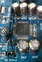
see bottom its SA9227 pins
")
Hi,like most owner of this Weiliang (AK4495 + AK4118 V.1.1) board, I was wondering what those dip switches function was. As it was difficult to follow the tracks on the PCB, I unsoldered the dip switch and discovered a design mistake: the PCB is designed to receive two jumpers, not a dual dip switch. If you look at the photos, you will notice that the right dip switch is short circuited by a track (which is tied to Vdd : High Level), you’ll also notice the two soldering hole of the left dip switch are both tied to resistors (pull down resistors) .That means the two dip switches are useless. The switches (or jumper) have to be installed first one: between hole identified 1 and 2, and second one: between the two other soldering hole.
Thank you for your observations old man AIM65.
So I was kidding myself. I must have switched those damned things fifty times.
I'll be interested to read what you do with yours (low ESR caps ect.)
Merci, Fidel
AIM65,
I am thinking of buying this board, what is your opinion do you recommend it? Elaborate if you can.
Thanks.
Dear ttan98,
When I bought this board, six months ago I knew I had to improve it: I wanted to have more coax inputs, a remote control and a nice enclosure. Thus the scope of the project was much wider than assembling a kit made of a board, a transformer and an enclosure. Work is still in progress, I’m currently finishing Arduino programming, and I miss time.
I was initially thinking to replace the 8051 controller of the board by an Arduino and to take overall control on the board, switches, display, input selector, volume etc.…, I went disappointed when I discovered that the 4495 was operating in parallel mode. Parallel mode mode restricts functionalities of the 4495 including DSD and volume control! I'm still using an Arduino to control the DAC but with limited scope.
Part of fun for me is to build the overall system. So, yes the board is good for this purpose, because I've to do some reverse engineering, but it depends on what you’re looking for.
My board sounds great, far much better than internal DAC of my various devices. I won’t be more specific because I’ve no benchmark with high end devices and my amp, speakers and room are good but not excellent.
At the end, pcb quality is good, soldering ok and components are from major brands, unless those are fake…
If I have to buy a DAC today, I’ll choose the new Asahi Kaisei Flaghship (AK4490) with AK4118 for SPIDF both serially managed in order to access all their functionalities and an USB to I2S board (XMOS or Amanero) in order to try HD Audio and DSD. But currently you may find very interesting boards (on paper) with 4495/4118/DSD/USB/SPIDF/COAX as the one identified by skrstic in post #60.
My board sounds great.thanks AIM65 for saving us. from the beginning the sound was awful and still is.
the #1 connection of DIP switch is already shortage on the board. if we rotate the switch %90 we maybe can take the chip from Slow rull off Mod? right?
Nosian,
Yes, 90° rotation of the switch is the solution, but the pcb layout doesn't fit this configuration. Instead you may use jumpers. See picture where SLOW is Low and SD High (jumper is installed). That's the default config : short delay-slow sharp roll off filter.
But if filtering is not the solution and sound is really awful you may have some saturation issues.
Output level of this board is high; you may try a 'quick and dirty' test : insert 220k pot between one output of the dac and the input of your amp to lower the input level and appreciate sound quality.
You may also check the analog stage power supply, you shoud have +15v in pin 8 and -15 in pin 4 of the opamp. You may also try to change the opamp.
Attachments
DAC gain is big, I have 10k pot between the headset and DAC. 220k is too big. I have tried with 50k, 10k is better.
AIM65 is there a way to change parallel control mode and this board can support DSD.
skrstic,
You're right, but I was talking of a 220k potentiometer in order to make some trials and tests, because it depends on the input impedance of the device connected. For example my amplifier has a 100k one, using a 10k won't produce any audible effect.
About DSD, I've to check, because:
- I'm pretty sure the AK4495 implemented on our boards could'nt handle DSD on his DSD input pins,
- I'm not sure at all of what is doing the USB daughter board. As AK4118 or AK4495 only support I2S(PCM) inputs, DSD stream coming from the PC has to be converted to I2S. Does the daughter board do this ?(mine is XMOS) I don't know. Is DoP (Dsd Over Pcm) the solution, I don't think so as DoP seems to be dedicated to the transport of the DSD stream over and existing PCM chain. ( see : DoP open Standard | DSD-Guide.com )
does anybody have an idea ?
Nosian,
Yes, 90° rotation of the switch is the solution, but the pcb layout doesn't fit this configuration. Instead you may use jumpers. See picture where SLOW is Low and SD High (jumper is installed). That's the default config : short delay-slow sharp roll off filter.
Aim65 thanks for sharing. With the dip switch, am I right to say the DAC is always set to sharp roll off filter?
Can you tell what the 2 filters provided by the soft switch do in relation to the jumper settings?
The DAC sounds great as it stands, noticeably better than earlier Asahi Kasei DAC chips.
Last edited:
Bernie7
yes, sharp roll filter (with sslow mode) is the current setup.
Parallel mode (hardware) setup and Serial (soft) setup do the same things. But scope of functionnalities with serial mode is wider than in parallel. Rather than paraphrase the datasheet, may I suggest you to download it, I cant' attach it : it's too big attachement. Please read :
- In p28, parallel mode filter config
- In p30, serial mode filter config
- In p44, serial / parallel function list
- In p49, register mapping (serial mode) where you can identify the 3 bits involved in filter configuration : SD, SLOW and SSLOW. In parallel mode those bits are 'tied' to the pins, respectively, 7, 8 and 5.
Interesting..The DAC sounds great as it stands, noticeably better than earlier Asahi Kasei DAC chips.
I can not hear any difference between AK4396 and AK4490, with same analog output..
Aim65 I will have to mod that dip switch. Instead of replacing it with jumpers I might just cut traces, reconnect two pins and retain the dip switch. We'll see if that can be easily done.
Vuljove I'm very familiar with ak4396. For me the standout of ak4495 as implemented on this board is greater refinement in the highs and better separation of singers, instruments.
Mods I've done so far...added tantalum bypass caps to the power supplies of the opamp soldered directly to its socket pins, and changed opamp to 627.

Filter set to Slow roll off, Short Decay thanks to Aim65's insight
Changed dip switch to jumpers rather than rewire the board as more than 2 tracks were involved and I couldn't be sure in this multilayer board. Notice the opa627, to the right of which I used 2 Silmic 25v47uf caps. Below the opamp I fixed small 15pf tantalum caps between +V and ground, -V and ground, and between + V and - V. Why 15pf? I had them lying around, higher values should be fine.
Simple mods, but you'll need some experience to remove the dip switch as you don't want to overheat the dac chip connected besides it.
Bernie7,
Whats your opinion on the LM49860 shipped with the board, and what make you choose the OPA627 ? Did you try other opamp ? I can see many threads about opamp choice.
I was evaluating the DAC through opc's The Wire headamp with LDR 'Lightspeed' attenuator and on this setup through my iem LM49860 sounded a bit strident. OPA627 was less so and more analog sounding to my ears. This was after playing the
LM overnight, with longer run in it may improve, who knows.
I've tried rolling other opamps in my ak4396 DAC before such as LM4562, OP275, NE5532, OPA2132/34, OPA2604, LME49720, OPA2227 but always came back to OPA627. They say the metal can LME49710 is very good but I've not tried it.
Last edited:
Mods I've done so far...added tantalum bypass caps to the power supplies of the opamp soldered directly to its socket pins, and changed opamp to 627.
Thanks, I was thinking of this mod.
- Status
- This old topic is closed. If you want to reopen this topic, contact a moderator using the "Report Post" button.
- Home
- Source & Line
- Digital Line Level
- Finally Weiliang released ak4495+ak4118 dac today.