Wow, I'm a little confused ( well that's normal ). I'm not an engineer, but I am a tech. Built research test equipment for NASA for the past 30 yrs. If the connectors are in correctly, and the wire is not pinched anywhere, what difference dose it make if the cable is not straight and flat? Even in the picture, nothing seems pinched, and if the connectors are in place correctly, Why is this a bad way to run the cable from brd. to mechanics? I'm not knocking anything you say. I'm just curious. I do learn new stuff once in a while. Like I have never heard in my time working for NASA, That mounting the SMD capacitors on their side makes for less noise. Even asked a bud, that does nothing but assembly of Flight equipment( stuff going into space) and he never heard such a thing either. So I eager to learn more. Thank you.
Well I'm an engineer and I would like to build equipments for NASA.

In my comment above I'm referring to ribbon cable from optics to main board. This is a semi-rigid cable and if is twisted like in the picture will limit optics movement, therefore CD reading will be highly affected. Beside this, the force generated by twisting this cable will make CD tracking very slow.
About mounting capacitors on their side.
These are MLCC - Multi Layer Ceramic Capacitors. Each capacitor is a sandwich. Most used dielectric in these capacitors is X7R and X5R, because is cheap and allow high capacitance in low volume. The down side is that these capacitors are highly piezoelectric. That mean any vibration on the PCB will be transmitted to these capacitors. And because we listen to music there will be a wide range of vibrations.
These capacitors have very low ESR/ESL and we use them to decouple IC's in order to kill any noise and smooth voltage.
But due piezoelectric effect we also induce a lot of noise in IC's main power rails.
The solution is to mount these capacitors on the side. This was demonstrated already and is not my "invention".
Next question is obvius : Why all manufacturers are not using on side mounting ?
Because all mounting is automated and parts have not designed to be mounted on side.
A quick search on the internet will reveal a lot of tests and documentation. For example see Singing Capacitors (Piezoelectric Effect) | FAQ | Multilayer Ceramic Chip Capacitors | TDK GLOBAL Q5
"Capacitors also have parallel self-resonance frequencies, related to the way they are manufactured and mounted on a PC board. There is only one series resonant frequency, but
there are a series of parallel capacitances. A rough rule of thumb is that the first parallel resonant frequency occurs at about twice the series resonant frequency."
See attached document.
And at the final, the parasitic capacitance between any PCB trace who pass under MLCC capacitor is minimized as well by mounting on side.
So, you have now at lesat three reasons to mount capacitors on side. Whatever equipment you design for NASA, mounting MLCC caps on side will improve performance. I really hope that Shiga MKII have learned you something and NASA will get better equipments from now. ;-)
Regards,
Tibi
Attachments
Last edited by a moderator:
I found such info but can't confirm
Could be used, but some modifications need to be made - from what I see optical connector is reversed. So, this SF-P102 is not a direct replacement in Shiga MKII or original JVC.
Regards,
Tibi
Well I'm an engineer and I would like to build equipments for NASA.
In my comment above I'm referring to ribbon cable from optics to main board. This is a semi-rigid cable and if is twisted like in the picture will limit optics movement, therefore CD reading will be highly affected. Beside this, the force generated by twisting this cable will make CD tracking very slow.
About mounting capacitors on their side.
These are MLCC - Multi Layer Ceramic Capacitors. Each capacitor is a sandwich. Most used dielectric in these capacitors is X7R and X5R, because is cheap and allow high capacitance in low volume. The down side is that these capacitors are highly piezoelectric. That mean any vibration on the PCB will be transmitted to these capacitors. And because we listen to music there will be a wide range of vibrations.
These capacitors have very low ESR/ESL and we use them to decouple IC's in order to kill any noise and smooth voltage.
But due piezoelectric effect we also induce a lot of noise in IC's main power rails.
The solution is to mount these capacitors on the side. This was demonstrated already and is not my "invention".
Next question is obvius : Why all manufacturers are not using on side mounting ?
Because all mounting is automated and parts have not designed to be mounted on side.
A quick search on the internet will reveal a lot of tests and documentation. For example see Singing Capacitors (Piezoelectric Effect) | FAQ | Multilayer Ceramic Chip Capacitors | TDK GLOBAL Q5
"Capacitors also have parallel self-resonance frequencies, related to the way they are manufactured and mounted on a PC board. There is only one series resonant frequency, but
there are a series of parallel capacitances. A rough rule of thumb is that the first parallel resonant frequency occurs at about twice the series resonant frequency."
See attached document.
And at the final, the parasitic capacitance between any PCB trace who pass under MLCC capacitor is minimized as well by mounting on side.
So, you have now at lesat three reasons to mount capacitors on side. Whatever equipment you design for NASA, mounting MLCC caps on side will improve performance. I really hope that Shiga MKII have learned you something and NASA will get better equipments from now. ;-)
Regards,
Tibi
I hope NASA continues to mount them flat and that they have counted on the possible negative effects of doing that. The global spaceprograms does not need more failures if they can be avoided - better to create a bit bigger boards if necessary. On earth with constant G - the document is interesting...
Regards
Well I'm an engineer and I would like to build equipments for NASA.
In my comment above I'm referring to ribbon cable from optics to main board. This is a semi-rigid cable and if is twisted like in the picture will limit optics movement, therefore CD reading will be highly affected. Beside this, the force generated by twisting this cable will make CD tracking very slow.
About mounting capacitors on their side.
These are MLCC - Multi Layer Ceramic Capacitors. Each capacitor is a sandwich. Most used dielectric in these capacitors is X7R and X5R, because is cheap and allow high capacitance in low volume. The down side is that these capacitors are highly piezoelectric. That mean any vibration on the PCB will be transmitted to these capacitors. And because we listen to music there will be a wide range of vibrations.
These capacitors have very low ESR/ESL and we use them to decouple IC's in order to kill any noise and smooth voltage.
But due piezoelectric effect we also induce a lot of noise in IC's main power rails.
The solution is to mount these capacitors on the side. This was demonstrated already and is not my "invention".
Next question is obvius : Why all manufacturers are not using on side mounting ?
Because all mounting is automated and parts have not designed to be mounted on side.
A quick search on the internet will reveal a lot of tests and documentation. For example see Singing Capacitors (Piezoelectric Effect) | FAQ | Multilayer Ceramic Chip Capacitors | TDK GLOBAL Q5
"Capacitors also have parallel self-resonance frequencies, related to the way they are manufactured and mounted on a PC board. There is only one series resonant frequency, but
there are a series of parallel capacitances. A rough rule of thumb is that the first parallel resonant frequency occurs at about twice the series resonant frequency."
See attached document.
And at the final, the parasitic capacitance between any PCB trace who pass under MLCC capacitor is minimized as well by mounting on side.
So, you have now at lesat three reasons to mount capacitors on side. Whatever equipment you design for NASA, mounting MLCC caps on side will improve performance. I really hope that Shiga MKII have learned you something and NASA will get better equipments from now. ;-)
Regards,
Tibi
Tibi,
Thank you for that explanation. I am no longer confused. Well, at least about this. And it helped me out . I need to do a slight redesign, to my chassis now to accommodate this cable. Thank you again.
Tony G.
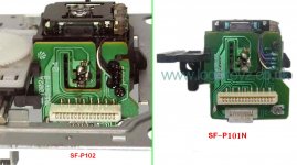
In PHILIPS MCM8/22 pickups SF-P102 and SF-P101N can replace
as russian forum confirms.So they are after all similar in point of pin to pin view.
According to your previous post http://www.diyaudio.com/forums/digi...kii-black-builders-thread-76.html#post4023642 , ribbon cable may need to be reversed ... but this is only a guess as I never seen SF-P102.
Anyhow, thanks for this info.
Regards,
Tibi
It Lives !!!
I just put together the Shiga High grade Pre built and tested kit. It has none of the laser mods done yet. I wanted to see how it sounded this way, before I do the laser mods, and add V1, and V2 regulators. Now, I'm playing this through a Jolida Glass FX Tube DAC, and a 20 year old Denon integrated amp and 20 year old Mirage 2 way book self speakers. And I'm listening near field in a cluttered 10'x10' shop. However I used a Cars CD, "The Cars", I think it was their first. It's a gold CD, that's always sounded great. All I can say is WOW. I got into tube rolling in the DAC, and I really had to force myself to turn it off. I couldn't stop listening. And I haven't even done the WOW, and HOLY **** Mods yet. I can't wait to get this system complete. When it's done it will be Shiga High grade, Moded Jolida Glass FX Tube DAC, Tube Lab 300B amp with separate power supply with no electrolytic capacitors in it, through a pair of slightly modified Madisound BK-16 back loaded horns. As soon as it cools off enough around here to put a finish on the speakers, and the wood chassis for the amp and DAC. I can get this all done. I will post pictures when I'm done. Thanks for listening.
I just put together the Shiga High grade Pre built and tested kit. It has none of the laser mods done yet. I wanted to see how it sounded this way, before I do the laser mods, and add V1, and V2 regulators. Now, I'm playing this through a Jolida Glass FX Tube DAC, and a 20 year old Denon integrated amp and 20 year old Mirage 2 way book self speakers. And I'm listening near field in a cluttered 10'x10' shop. However I used a Cars CD, "The Cars", I think it was their first. It's a gold CD, that's always sounded great. All I can say is WOW. I got into tube rolling in the DAC, and I really had to force myself to turn it off. I couldn't stop listening. And I haven't even done the WOW, and HOLY **** Mods yet. I can't wait to get this system complete. When it's done it will be Shiga High grade, Moded Jolida Glass FX Tube DAC, Tube Lab 300B amp with separate power supply with no electrolytic capacitors in it, through a pair of slightly modified Madisound BK-16 back loaded horns. As soon as it cools off enough around here to put a finish on the speakers, and the wood chassis for the amp and DAC. I can get this all done. I will post pictures when I'm done. Thanks for listening.
Hi Guarena.
Sound very interesting setup. 300b power amp with no sound cap? Does it runs interstage? Cant wait to see your Shigaclone complete built. Are you mounting on any chassis/enclosure? Or bare? Please dress them up.
Thanks.
The amp does have signal caps, they just aren't electrolytic. I replaces 4 electrolytic caps with MCap Poly tube caps. Electrolytic caps are evil. About my Shiga, I call it "THE Anchor". It's heavy. I believe in Mass/weight, = less vibration. I had some thick copper laying around in my shop. So I made a box with a 1.5" thick,x 6" long x 3.25" wide copper plate for the bottom, with .5" thick x 6"long,x 4" high Bronze plates on the sides, and .5"x 4.5"x 4" copper plate on the back. All bolted together with brass socket head cap screws. The main board is mounted on the back copper plate, and the CD mechanics is mounted inside at the top of the box on .5" x .75" x 2.5" copper stand off I made, which bolt to the box through the bottom and side. The mechanics is mounted to the standoffs with a grunge buster washer between the standoff and mechanics, and one on top, with a copper washer on top of that, held in place with a brass screw. Even the brd is held on with brass screws, copper washers and nylon standoffs. Now I have to make the box for it, to match the ones I made for the amp and it's power supply. When I'm done I will post pictures. Thanks for listening.
The amp does have signal caps, they just aren't electrolytic. I replaces 4 electrolytic caps with MCap Poly tube caps. Electrolytic caps are evil. About my Shiga, I call it "THE Anchor". It's heavy. I believe in Mass/weight, = less vibration. I had some thick copper laying around in my shop. So I made a box with a 1.5" thick,x 6" long x 3.25" wide copper plate for the bottom, with .5" thick x 6"long,x 4" high Bronze plates on the sides, and .5"x 4.5"x 4" copper plate on the back. All bolted together with brass socket head cap screws. The main board is mounted on the back copper plate, and the CD mechanics is mounted inside at the top of the box on .5" x .75" x 2.5" copper stand off I made, which bolt to the box through the bottom and side. The mechanics is mounted to the standoffs with a grunge buster washer between the standoff and mechanics, and one on top, with a copper washer on top of that, held in place with a brass screw. Even the brd is held on with brass screws, copper washers and nylon standoffs. Now I have to make the box for it, to match the ones I made for the amp and it's power supply. When I'm done I will post pictures. Thanks for listening.
Hi Guarnena,
Mass - vibration recalls me of my long time project dealing with Lenco 75 with huge layered plywood. That:
Sanyo mechanism very similar to Ideal roller Turntable - Lenco 75, 301,401 - needs mass or solid plint.
CDM very similar to LP12, suspension and light weight.
I have 2 small pieces of corian (imitation marbel) which I plan to use as top cover for this project. I can't make entire chassis out of metal material because don't have the machine to cut accordingly except drilling some holes. I happened to come across someone selling locally a Harmond enclosure. This case, I will replace the cover with if possible -thick corain, or otherwise acrylic which cutting is not an issue. The mechanism will mount from bottom of the cover, and the mainboard will sit inside the enclosure. Still, I have issue to cut for the LCD board. I bet your Shigaclone will looks mighty and awesome since resonance is your main concern. Please share your progress here.
All the best.
Last edited:
I Screwed Up.
Well, things were going just fine. I finished the laser mods, everything worked fine, and it sounded great. Until I decided to change C8 to my Copper foil V.Cap. I pulled the EVO cap and soldered in the V-Cap. Nothing. Would not read disk, or do anything. Just two zero's in the display. So I inspected, soldered it again to make sure, still nothing. So I put the EVO back in, and it worked again. Not wanting to give up, I measured the V-Cap. .1uf exactly. Put it back in, still nothing. I removed it and put the EVO back. Now, nothing with the EVO cap in place. Buy now I completely lifted the pad from C8 to pin 10 on LA9242M. I put a little jumper from the copper trace going to pin 10 to the end of C8, so I know I have a connection from C8 to pin 10 on the LA9242M. The trace from the other end of C8 is OK and makes connection with c30, c36, and c37 etc. Still nothing. I'm stuck. I don't know what to do. I don't wand to mess up the Board anymore, and I can't get it to work.
Tibi,
Is there anyway I can buy another main board, high grade, that works, and I'll leave the C8 cap alone. I promise!
Scew Up
I'm looking at the brd. under a microscope, and doing a little buzzing. One end of C8 goes only to pin 10 of LA9242A and no where else according to the schematic. I had that connection. I know, because I buzzed it from the cap lead to pin 10. The other end of C8 follows a trace that seems to go to all the places shown on the schematic. So why can't I get it to work? Banging head on work bench. I would hate to have to scrap this brd. It's a high grade, and it has a lot of good parts on it. And it's gonna be really tight trying to get up enough $$$ for a new high grade brd. Sh&t, I should of left well enough alone, but who would of thought that a simple cap swap would cause so much trouble. Figures, I was to happy, when I did the laser mods, and they worked.

I'm looking at the brd. under a microscope, and doing a little buzzing. One end of C8 goes only to pin 10 of LA9242A and no where else according to the schematic. I had that connection. I know, because I buzzed it from the cap lead to pin 10. The other end of C8 follows a trace that seems to go to all the places shown on the schematic. So why can't I get it to work? Banging head on work bench. I would hate to have to scrap this brd. It's a high grade, and it has a lot of good parts on it. And it's gonna be really tight trying to get up enough $$$ for a new high grade brd. Sh&t, I should of left well enough alone, but who would of thought that a simple cap swap would cause so much trouble. Figures, I was to happy, when I did the laser mods, and they worked.
Do the CD spins ? It can be also the laser fault after modified.Try to change it with an unmodified if you have one.Well, things were going just fine. I finished the laser mods, everything worked fine, and it sounded great. Until I decided to change C8 to my Copper foil V.Cap. I pulled the EVO cap and soldered in the V-Cap. Nothing. Would not read disk, or do anything. Just two zero's in the display. So I inspected, soldered it again to make sure, still nothing. So I put the EVO back in, and it worked again. Not wanting to give up, I measured the V-Cap. .1uf exactly. Put it back in, still nothing. I removed it and put the EVO back. Now, nothing with the EVO cap in place. Buy now I completely lifted the pad from C8 to pin 10 on LA9242M. I put a little jumper from the copper trace going to pin 10 to the end of C8, so I know I have a connection from C8 to pin 10 on the LA9242M. The trace from the other end of C8 is OK and makes connection with c30, c36, and c37 etc. Still nothing. I'm stuck. I don't know what to do. I don't wand to mess up the Board anymore, and I can't get it to work.
Tibi,
Is there anyway I can buy another main board, high grade, that works, and I'll leave the C8 cap alone. I promise!
Screw up
I have a hard time posting photo's. Please don't ask. The brd is a pre assembled and tested high grade brd. Looks standard except where I lifted the pad. I don't have a non modified mechanics to try. As it stand now the CD does not spin, just two zero's on the display. If it is the mechanics, then it's intermittent. It played fine after the mod, and after I hot glued the parts down. And after I put the EVO cap back in the first time. But know nothing. If you think its the mechanics, I'll order a couple more. Any help, or theory's would be appreciated. Thank you all.
Tony G
Tony,
Please check ribbon cable to be properly inserted on both ends.
Regards,
Tibi
PS. Sorry for late response. I'm in a area with limited internet access.
Hi Tibi,
The ribbon cable is fine. I have ordered 5 new mechanics, so I will have a known working mechanics. What I could use is a couple of more ribbon cables from brd. to motor of mechanics. The 6 wire one with the white connector on each end. I had some wires break from taking in and out to much, and had to repair. But just in case it is part of the problem, I'd like to avoid as many variable as I can. So if you pay pal me an invoice for 2 or 3 more of these cables I will get that plus shipping to you ASAP. Let me know if you need my email if you don't have it on file. Thanks.
Sincerely,
Tony G.
- Home
- Source & Line
- Digital Source
- Shigaclone MKII Black - The builders Thread