Hi niffy
Considering my limited knowledge of the Metric System, 2,640.00g strikes me as being a shade on the heavy side. Are you sure that a decimal error didn't creep in there somewhere?
Sincerely,
Ralf
Just weighed my arm and measured its centre of mass.
2.64kg.
Niffy
Considering my limited knowledge of the Metric System, 2,640.00g strikes me as being a shade on the heavy side. Are you sure that a decimal error didn't creep in there somewhere?
Sincerely,
Ralf
Hi Paul and Ralf.
The arm was made massive for several reasons.
Firstly for the obvious rigidity reason. The more solidly the rail on which the carriage runs is held the better the sound quality.
Secondly, due to where it will live, I am making a deck with suspended suspension. Linear tracking tonearms are normally thought to be unsuited to this type of deck. This is because the mass of the carriage as it traverses the record slightly moves the centre of mass of the deck. This causes the sub-chassis to tilt moving the rail from horizontal. Differing weights of records have the same effect as well. By making the platter/arm/sub-chassis heavy the proportion of the mass made up by the carriage is reduced. This reduces the amount of tilt. Increasing the distance between the points of suspension also helps. My calculations and experiments suggest that the deck will tilt by a couple of arc minutes at worse. Not enough to worry about, I've purposely tilted the rail by twice as much and I couldn't hear a difference.
Thirdly. The mass and location of the centre of mass of the arm also allows me to align the centre of mass of the suspended portion of the deck with the geometric centre of suspension and the centre of the drive system. I've tweaked a suspended deck towards this before and it really opened the sound up. As I'm scratch building this deck I should be able to get them to coincide precisely.
Fourthly. The alignment adjusters are very solid so I don't have to worry about the arm drifting out of alignment. Once I've finished building the deck I just want to listen to music on it, I don't want to be constantly readjusting.
Lastly. I think it looks great.
Niffy
Hi Niffy ,
Thanks for the clearification ! I hear you") ....
....
I'm pretty much interesting in your suspension methode .. is it a freq. tuned system ? I mean ... given your measurings I assume you are trying to set the
suspension at a certain freq. for the complete system . I like the idea of progressive suspension with oil dampers or the like .
Interesting stuff indeed !!
THX
Paul
Thanks for the clearification ! I hear you
.... I'm pretty much interesting in your suspension methode .. is it a freq. tuned system ? I mean ... given your measurings I assume you are trying to set the
suspension at a certain freq. for the complete system . I like the idea of progressive suspension with oil dampers or the like .
Interesting stuff indeed !!
THX
Paul
Hi Niffy ,
Thanks for the clearification ! I hear you
I'm pretty much interesting in your suspension methode .. is it a freq. tuned system ? I mean ... given your measurings I assume you are trying to set the
suspension at a certain freq. for the complete system . I like the idea of progressive suspension with oil dampers or the like .
Interesting stuff indeed !!
THX
Paul
Hi Paul.
I am setting the suspension frequency at 3hz.
The deck will hang from 3 springs spaced at 120degrees. The centre of mass coincides with the geometric centre of the suspension. The suspension is fine tuned by adjusting the length of the springs. I have found that this type of suspension work best completely undamped. The springs will be attached to the sub-chassis inside of tubes. The tubes will be partially filled with low viscosity silicone fluid (100cs) to cover only the bottom third of the springs. This is adequate to damp all the other vibration modes of the springs but has virtually no damping effect on the suspension itself.
I've just been doing a bit of fine tuning for the design of the sub-chassis and everything seems have come into perfect alignment really easily. I was using an iterative design process and had expected to need 3 or 4 iterations before the design converged. My initial guess put the centre of mass less than a millimetre from the geometric centre of the suspension, lucky guess.
Niffy
Hi Niffy ,
At some point , I'll definitely work out a suspended TT to see how it stands against a mass unit . keep us posted about your results , please , as I believe it can make a world of a difference as soon as a TT system is well dampened .
may I say .. critically dampened ?
THX
Paul
plenty ideas to work out ... please don't forget this one :
Analog Planet September 2012 | Audio Vibration Isolation Stands for Turntables & Audiophiles
Hi Paul.
Thanks for the link. Most interesting reading. Some good points were made especially in the opening couple of paragraphs.The most interesting part was the animated diagram at the top of the article. It's completely back to front, the base is stationary and the shelf is wobbling all over the place. The whole idea of an isolation platform is that the shelf stays still whilst the world, and the base, jiggles about. It's an understandable mistake, prod a suspended turntable and the sub-chassis bounces around.
If the sub-chassis is bouncing relative to a stationary earth then you do want damping to bring the sub-chassis to rest. However it is the sub-chassis you want to keep stationary as the earth jiggles about. By adding damping in this case you are actually trying to damp the motion of the entire earth relative to the stationary sub-chassis.
The point in the article about the torque reaction between the motor and the suspended sub-chassis is also important. Again this occurs because the wrong reference point, the Earth, is used.
Again the subchassis should be the reference. Isolate the earth from the sub-chassis and isolate the motor from the sub-chassis. Eg mount the motor on the sub-chassis using a compliant coupling. No torque reaction, no jiggling of the sub-chassis so no need for damping of the suspension. There are further good reasons to mount the motor on the sub-chassis that I can go into if you wish.
In fact when you mount a solid plinth deck on an isolation platform the plinth essentially becomes the sub-chassis with the motor mounted on it.
You can probably guess that my deck is going to have a sub-chassis mounted motor. The motor is located at the very heart of the deck. It is mounted at the centre of mass/suspension of the sub-chassis. This helps to further prevent undesirable oscillations.
The sub-chassis design is pretty much complete, so hope to be starting to build soon.
Niffy

Hi Colin ,
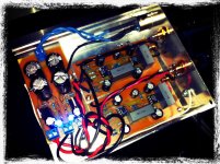
Thanks for the pics ! great building quality .. short path .. decent wiring etc.
great job ! I see lots of MF resistors .. were you hunting for the lowest noise numbers / acuracy ? I play/switch a lot with resistors in order to tune the sound !
I must admit that I never ever build an IC phono amp ever
I'm following Sala's thread closely over the years but not build yet .
THX
Paul
Hi Niffy ,
I admire you'r consistency in every respect ! Not afraid to do the math and work out for a better TT system . Suspension is a tough challenge given the complexity and many sidetracks , but I believe that it's exactly there where we can improve things soundwise . movements on microscopic scale should be avoided like the plaque , right ?
THX
Good Luck !
Paul
Thanks Paul.
The numbers are converging better than I had hoped. I should end up with an amazingly effective suspension system (if my theories are correct)
Right!
The cartridge is an ultra-sensitive vibration detector after all.
Niffy
The numbers are converging better than I had hoped. I should end up with an amazingly effective suspension system (if my theories are correct)
movements on microscopic scale should be avoided like the plaque , right ?
Paul
Right!
The cartridge is an ultra-sensitive vibration detector after all.
Niffy
I spent some hours over the last weekend reading approx. 130 posts but my attention span didn't get me to the last post, sorry. Firstly let me say well done to VA and others that have built this project and been happy with the results, it surprises me that something rolling/sliding on one edge of a bearing albeit four bearings left loose laterally I assume and sliding vertically can produce great sound, but then what some consider great is not what those golden eared ones would agree is great. Now I for one cannot tell much difference between a voyd TT and my 401 and cannot hear any difference between my 9" unipivot and my 12" unipivot so I don't include myself in the golden eared club. Looking at clearaudio's effort at $10k of two bearings rolling/sliding inside a glass tube as opposed to outside cannot be much better in my opinion. How much friction is required to get the bearings to roll and not slide has to do with how much force is applied to the bearings and then sufficient force would probably cause the cantilever undue stress, a vicious circle that those here have overcome it seems. So well done to all. I am embarking on a slightly different approach, not so different and you may all snigger and say, " yeah been there, tried that " I am going to try a linear bearing and ground steel shaft, 6mm diameter mounted in a clearaudio style of two tie rods above the carriage rod with two end plates. Now the same may apply that sufficient force for the bearings to roll and not slide may be too much for the cantilever, but it must be tried. First will be to see how a linear bearing cleaned of all grease/oil moves on the shaft and then how much better it will move on half that shaft being polished against the other half. I am thinking if this first part seems to work then a very short almost no wand will be used. Thoughts anyone?
Linear Bearing
I've often thought of using one for an arm. I've seen pictures of one from the Far East-Japan I seem to remember. From other contributions elsewhere, I believe that the friction of these is going to be a problem-but hey-if you never try it, you'll never know.
Chris
I've often thought of using one for an arm. I've seen pictures of one from the Far East-Japan I seem to remember. From other contributions elsewhere, I believe that the friction of these is going to be a problem-but hey-if you never try it, you'll never know.
Chris
I am going to try a linear bearing and ground steel shaft, 6mm diameter mounted in a Clearaudio style of two tie rods above the carriage rod with two end plates.
I've seen pictures of one from the Far East-Japan I seem to remember.
>- - - -> Japanese website on linear tonearm using linear bearing
Joe the LBBR3 bearing from SKF is 0.7gr according to the pdf, while the 3x10x4 simple bearing is 1.5gr... and we need 2 or 4
OK the shaft for LBB3 has to be 3mm, but only the screws and the nuts on Cantus design should weigh more than that. In fact, 2x m3 screws 20mm long and 2 nuts weigh for me 1,8gr. Add to that 6 grams for the bearings ( from the skf pdf) and we go to 7,8grams, still with no washers or brass tubing.
So not counting some stuff, we could use the LBBR 8 for an 8mm rod and still be on slightly less weight. Not to mention that the T polycarbonate part does not have to be that big any more.
Anyway. I do not mean to hijack the thread. I am just exploring different and maybe simpler approaches since I am having trouble finding the bearings locally. Since I am going to the industrial parts store, I might as well check the optioIns there
I will probably build both eventually
What troubles me is that linear bearings usually run tightly on the rod, and that they have a breaking in period. Perhaps a 8mm bearing on a 7mm rod?
I don't think there will be any improvement using flexible parts in the carriage since it should only be able to move freely sideways and be able to rotate (slightly) on the tube. Any other movement is bad...
Brgds
They do have ball bearings in them so shouldn't be too much friction, depending on the tightness to the shaft, with some movement should only be touching on a small amount of the balls, time will tell.I've often thought of using one for an arm. I've seen pictures of one from the Far East-Japan I seem to remember. From other contributions elsewhere, I believe that the friction of these is going to be a problem-but hey-if you never try it, you'll never know.
Chris
Hi Colin ,
Thanks for the pics ! great building quality .. short path .. decent wiring etc.
great job ! I see lots of MF resistors .. were you hunting for the lowest noise numbers / acuracy ? I play/switch a lot with resistors in order to tune the sound !
I must admit that I never ever build an IC phono amp ever
I'm following Sala's thread closely over the years but not build yet .
THX
Paul
Thanks Paul,
You would think using ic's would simplify things, not the case at all in reality. It took a lot of rolling, resistor/capacitance ratios, gain mods, and power supply tests to come up with this. After all how easy has it ever been to combine the punch and precision of Solid state with the harmonic richness of tubes without raising noise?. It's basic operation is similarity use in the Vendetta, but wih a Fet input high slew op amp for the input and a high slew diamond transistor vfb op amp to the active stage. All the while paying meticulous attention to the feedback ratio for the active stage, too high = no life in a nutshell.
Colin
- Home
- Source & Line
- Analogue Source
- DIY linear tonearm