I'm not sure if I'll go that massive Niffy ") I need the surface area on the deck in the first place , but I'm ready to construct a whole new massive deck to accomodate the new dual rod arm thingy if necessary of course . the arm lift mechanism will not become part of the arm itself but a stand alone solid base piece , for obvious reasons , also because I want to make it a motorized unit battery feeded and push buttons . all in all .. I painted the rail support this time I want it to have a vintage industrial appearance . more pictures will follow soon ! ps: the stainless bars are only temporary .. the bronze or brass ones are coming soon .
I need the surface area on the deck in the first place , but I'm ready to construct a whole new massive deck to accomodate the new dual rod arm thingy if necessary of course . the arm lift mechanism will not become part of the arm itself but a stand alone solid base piece , for obvious reasons , also because I want to make it a motorized unit battery feeded and push buttons . all in all .. I painted the rail support this time I want it to have a vintage industrial appearance . more pictures will follow soon ! ps: the stainless bars are only temporary .. the bronze or brass ones are coming soon .
THX
Paul
I need the surface area on the deck in the first place , but I'm ready to construct a whole new massive deck to accomodate the new dual rod arm thingy if necessary of course . the arm lift mechanism will not become part of the arm itself but a stand alone solid base piece , for obvious reasons , also because I want to make it a motorized unit battery feeded and push buttons . all in all .. I painted the rail support this time I want it to have a vintage industrial appearance . more pictures will follow soon ! ps: the stainless bars are only temporary .. the bronze or brass ones are coming soon . THX
Paul
Attachments
Hi Paul.
Once again your finish quality is outstanding, good job.
Were you planning on making the powered lift/lower device remote control? I've always liked the idea of being comfortably settled in my listening chair before starting the record. I believe you said earlier in this thread that your main diy area was electronics/amplification so it's probably well within your capabilities to knock up an IR unit. Looking forward to seeing your next step.
Niffy
arduino controlled motorized arm lift / lower system
Hi Niffy ,
I was thinking a uP Arduino controller , small display etc. also .. I was meant to implement a stop sensor so that the arm automaticaly goes up at the end of the record .
Oohh , sure ! definitely remote controlled !
I think first I should get the arm going so I can adjust for optimum OP etc . than I'll customize it for comfort
THX
Paul
A New Rail
Hi Guys (and Gal, there must be one lady diyer out there somewhere)
I too have been busy.
When I modified my arm from the pin bearings/large wheels to two rod/ball race design the sound quality improved across the board. The only test the original set up came out on top in was the pencil tap test where the stylus is placed on a non-rotating record and the rail is tapped with a pencil. This shows how well the carriages support structure deals with any vibrational energy either from the cartridge end or the deck. Ideally the pencil tap should not be audible through the speakers at all.
With the original rail, thick walled stainless tubes and carbon fibre, the tap was not audible at normal listening levels. The note heard at elivated levels was low and decayed instantly.
The first two rod rail I made was supported in an acrylic channel. The tap test with this rail was just audible with the volume control set a bit over half way to normal listening level and had a higher more sustained note.
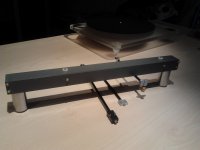
My latest bit of building has been to make a more substantial two rod rail.


As with the previous rail I am using 4mm glass rods separated by a 1.5mm carbon batton. The base of the rail is 3mm stainless steel. Two 6mm stainless steel tubes filled with low modulus silicone create the channel in which the rods sit. Aluminium end caps allow for solid mounting. As the rail passes through the carriage I was limited in the maximum size. A half millimeter flat needed to be filed of the inside edge of both of the 6mm tubes to reduce the overall width. This has been a really fidley thing to make.
Has it been worth it? It now passes the tap test with the volume needing to be way above normal listening for it to be heard and the note is lower and decay instant. The change in sound quality is quite noticable. I had expected the main difference to be at the bottom end. The bass has definatly improved but the improvements didn't stop there. Everythings a bit cleaner, the background darker with more air between instruments. Dynamics are sharpened but without harshness. The ability of this arm to be silky smooth and have lightning dynamics at the same time is beyond any arm I've ever heard. All in all a very worth while modification.
It really does show just how important a good solid base is. Pauls dual pillar mounting should really make a big difference if my mod is anything to go by.
I have also been playing with the effective mass of the carriage to see how this effects things. My conclusion here is that I had it Bang on the mark already so no mods here. I think I might have pushed this arm as far as it will go as I can't think of any way to improve it without starting from scratch. Time to start working on the rest of the deck.
Niffy
Hi Guys (and Gal, there must be one lady diyer out there somewhere)
I too have been busy.
When I modified my arm from the pin bearings/large wheels to two rod/ball race design the sound quality improved across the board. The only test the original set up came out on top in was the pencil tap test where the stylus is placed on a non-rotating record and the rail is tapped with a pencil. This shows how well the carriages support structure deals with any vibrational energy either from the cartridge end or the deck. Ideally the pencil tap should not be audible through the speakers at all.
With the original rail, thick walled stainless tubes and carbon fibre, the tap was not audible at normal listening levels. The note heard at elivated levels was low and decayed instantly.
The first two rod rail I made was supported in an acrylic channel. The tap test with this rail was just audible with the volume control set a bit over half way to normal listening level and had a higher more sustained note.
My latest bit of building has been to make a more substantial two rod rail.
As with the previous rail I am using 4mm glass rods separated by a 1.5mm carbon batton. The base of the rail is 3mm stainless steel. Two 6mm stainless steel tubes filled with low modulus silicone create the channel in which the rods sit. Aluminium end caps allow for solid mounting. As the rail passes through the carriage I was limited in the maximum size. A half millimeter flat needed to be filed of the inside edge of both of the 6mm tubes to reduce the overall width. This has been a really fidley thing to make.
Has it been worth it? It now passes the tap test with the volume needing to be way above normal listening for it to be heard and the note is lower and decay instant. The change in sound quality is quite noticable. I had expected the main difference to be at the bottom end. The bass has definatly improved but the improvements didn't stop there. Everythings a bit cleaner, the background darker with more air between instruments. Dynamics are sharpened but without harshness. The ability of this arm to be silky smooth and have lightning dynamics at the same time is beyond any arm I've ever heard. All in all a very worth while modification.
It really does show just how important a good solid base is. Pauls dual pillar mounting should really make a big difference if my mod is anything to go by.
I have also been playing with the effective mass of the carriage to see how this effects things. My conclusion here is that I had it Bang on the mark already so no mods here. I think I might have pushed this arm as far as it will go as I can't think of any way to improve it without starting from scratch. Time to start working on the rest of the deck.
Niffy
Hey Chronotis, what makes you think you're not welcome here? I think I can speak for all the participants in this thread and say that everyone is welcome and we all love to see as diverse a range of variations of the diy linear tracker as possible. In fact this thread has slowed down a bit of late so some new blood to kick some life back into it would be most welcome.
Niffy
Niffy
Niffy - very solid and beautiful build!
One question, though..... how do you lock the tube assy' in the front position?
Just a lock screw, or something more elaborate??
Hi AuroraB,


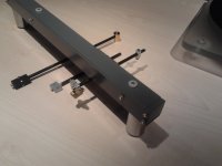
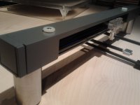
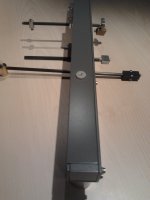
The decks not in the best location for taking photos, I hope these will do.
The stub that sits between the slide bars has a cut-out as shown in the first photo. The round knob on the upright, second photo, is attached to what is basically a rotating cam that turns into the cut-out pulling the stub forwards. A 180degree turn of the knob pulls the slide hard up against upright. Very simple mechanism, easy to use and effective.
Hope this explains it clearly enough, if not let me know and I'll try to clarify.
Thanks Niffy
Oh, you'll notice in the first photo that the slide doesn't sit flush against the side plate when it's in the rear position. This is on purpose, the rail tilts through several degrees as it is slid back so that the carriage will tend to roll to the outer end of the track and so the clearance between the end of the rail and the record increases. A couple of safety measures to protect both stylus and record.
Niffy
Niffy
Aha... thanks for the explanation. I did study the pic's you posted previously, but did not get that detail. Elegant solution.....
I've been pondering on a sort of swing arm solution to get the track out of the way for changing records. This seems like a very good solution to the problem. I think rigidity at this point is important.....
I've been pondering on a sort of swing arm solution to get the track out of the way for changing records. This seems like a very good solution to the problem. I think rigidity at this point is important.....
Hi AuroraB.
We're you thinking of swiveling the arm horizontally or vertically as with the clearaudio tt2? I like the vertical swivel design as it seems simpler and also more likely to maintain accurate alignment than the horizontal. I did contemplate this method of moving the rail but as I have two very inquisitive cats the deck has to live in a cabinet so total deck height is an issue for me. The slide system I chose came out as my preferred option not only due to the size issue but it also as it is very rigid and gave the simplest path for the arm cables.
Look forward to seeing what you come up with.
Niffy
Have been a little quiet of late, recently enjoying some RSD releases . Niffy, great work and highly intricate!. In this thread everyone is welcome, and everyone willing to build will have a design that suits them best, that's the beauty of Diy. The part I'm thoroughly satisfied with is that all of us building the concept are listening to very modestly priced MM cartridges and being graced with sonics that evoke descriptions usually reserved to ridiculously priced moving coils at times .
Colin
. Niffy, great work and highly intricate!. In this thread everyone is welcome, and everyone willing to build will have a design that suits them best, that's the beauty of Diy. The part I'm thoroughly satisfied with is that all of us building the concept are listening to very modestly priced MM cartridges and being graced with sonics that evoke descriptions usually reserved to ridiculously priced moving coils at times .Colin
Hi Colin ,
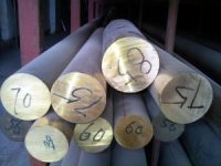
Agree ! I collected a bunch of MM and MI carts throughout the years which are very much in favor of most of my MC carts . this kind of LT arm is absolutely most suiting for high compliant carts . I'm a little biased with some moving iron Pickering and Stanton carts equiped with more sophisticated cantilever and diamond shape . stereohedron to name one .
My latest catch is a NOS Stanton 881MKII-S , aquired for 135 Euros , a steal if you ask me
THX
Happy Easter
Paul
Hi all.
I'm also in total agreement with Colin. My M2 blue is definitely punching way above its weight. Also on his point that you can design to suit your needs best. In diy you can do things that would be commercially unviable. I doubt if many of the arms shown in this thread would fit a standard deck without serious modifications. The ideal mounting location being in a completely different place than that required for a standard 9" arm for one. I doubt if there is a deck on the market that would take my arm. For instance the LTA adjuster is located at the bottom of the arm pillar and sits below the armboard and would be inaccessible on most decks. I've designed the record deck/arm as a single unit, right down to designing the whole thing around my choice of cartridge. I even took into account the location of the centre of mass of the cartridge to allow for better matching of effective mass and minimizing tracking force variations. A commercial arm designed for just one cartridge would not be popular.
My house has suspended wood flooring, very bouncy, and wall mounting of the deck is not an option. The final deck is going to have to have suspension. Now that I think the arm finished my next step is to weigh the arm and find its centre of mass. I already know the mass of the platter/drive. I can then design a chassis where the centre of suspension coincides with the centre of mass of the whole system. This allows the entire suspension to act as a single unit with big benefits for sound quality. A commercial deck designed for different arms of different masses just can't do this.
These are just a couple of my examples and I guess most of you could add to the list with your own designs.
DIY.
Niffy.
- Home
- Source & Line
- Analogue Source
- DIY linear tonearm