Hi Colin ,
I can see the complexity when using IC feedback loops , have you devided the
riaa over two stages ? and have you managed to get the output DC at save
levels , or did you decided to use a capacitor there ? tube noise usualy don't
bother me too much , but selecting the proper tube samples for gain and noise
can be painful I agree ;-)
I tried to find some details of the Vendetta Research phono amp but must read
through it to get an idea of the circuit + PS . Certainly worth some attention given
the great response .
Thx
Paul
Hi Paul,
It's spread over two stage with the second doing active 50.5 Hz pole and 500.5 Hz zero. The input amp since its fet with 30db of gain keeps offset low as seen by the next bipolar input. This output of the first also provides The input bias current needed so the output never goes above 1mv, no need for servo, plus servos are audible and I feel detract from the sound. No caps input to output, and in my whole system input to output there are only two series film caps before the speakers. Caps in itself aren't wholly bad, as long as they have a dc bias on them") . Both op amps are biased into heavier 9ma class a for plenty of drive especially on the first low impedence hf .2122khz passive pole, and yes the 50khz controversial zero is included .
. Both op amps are biased into heavier 9ma class a for plenty of drive especially on the first low impedence hf .2122khz passive pole, and yes the 50khz controversial zero is included .
Colin
It's spread over two stage with the second doing active 50.5 Hz pole and 500.5 Hz zero. The input amp since its fet with 30db of gain keeps offset low as seen by the next bipolar input. This output of the first also provides The input bias current needed so the output never goes above 1mv, no need for servo, plus servos are audible and I feel detract from the sound. No caps input to output, and in my whole system input to output there are only two series film caps before the speakers. Caps in itself aren't wholly bad, as long as they have a dc bias on them
. Both op amps are biased into heavier 9ma class a for plenty of drive especially on the first low impedence hf .2122khz passive pole, and yes the 50khz controversial zero is included .Colin
Hi all.
As my current workshop is in use, someones having a shower, I thought I'd show a quick update on my build and show a couple of pics of the arms alignment adjusters.
View attachment 418055
View attachment 418056
I've nearly finished making the router temlplates for the top of the sub-chassis and arm board as shown in the first photo. As the shapes used are irregular and I don't have a fancy CAD program to tell me the area/mass of the layers or where their centres of mass will be I had to be inventive. I printed the shapes on ordinary paper which were stuck onto thick cardboard and cut out. I also cut a 10cm square of the same paper/card and weighed it and from that obtained the mass per square cm. By weighing the shapes I was then able to ascertain the areas of the components. As I know the density and thickness of the matrial they will be made from I could then find the mass of the final component. Also by balancing the cardboard across a straight edge in several directions I easily found the COM. I have already measured the exact mass and COM of all the other components, arm etc, so easily found the centre of mass of the whole system. Within just a couple of iterations I have managed to aligned the systems centre of mass, centre of suspension, geometric centre of suspension, the motor, the centre of mass of the motor/mounting plate, the centre of suspension of the motor mounts and the geometric centre of susension of the motor mounts to within 0.6mm of each other. Hopfully this will yeild an almost perfect isolation of the sub-chassis. I stuck the seperate cardboard shapes together after I had finished measuring to get a better hands on feel of the finished item will look, except the final layers will be much thicker. This is shown in the second photo.
The adjusters for the alignment of the arm are shown in this second series of photos.


The main arm pillar is a 25mm diameter solid stainless steel bar. Lateral tracking angle is adjusted by rotating about this bar and vertical tracking angle/height is adjusted by raising and lowering it. Leveling the rail is acheived by rotating the entire upper section of the arm about a horizontal 12mm stainless bar. The two bars are locked in place by clinches as shown in the first photo. The two bolts on the square block lock the tilt adjuster, the 12mm bars end protrudes through the main upright. The two bolts on the circular base lock the main arm pillar.
The second photo shows the rail leveling adjuster. It has a grub screw that presses against the top of the main pillar and allows fine adjustment. the second countersunk bolt locks the adjuster in place once adjustments are finished.
The hole under the rail is for the VTA adjustment screw. Possitioning it here does mean that the rail has to be slid backwards to allow for it to be accessed so no otf adjustment is possible. I did contemplate an adjuster that allows for fine tuning for each record depending on thickness but this is just way to much hassle as every record has to have its ideal height determined and set to for each play. (this isn't as easy as just measuring the thickness of the record as warp height, cutting angle all effect ideal vta and would have to be determened by ear) I just want to listen not tweek so I'll set vta to a good average and leave it.
The Third photo shows the LTA adjuster. This sits below the sub-chassis. The main pillar passes right through the arm board and top plate and is also secured below. This makes for a very solid mounting of the arm. On the current tempary plinth this is a real pita to get to but on the finished sub-chassis it will protude and be easily accesable. A couple of grubs adjust and also lock this adjuster.
All of the adjusters only have a small range of movement but as the arm will only ever be used on one deck the range is more than adiquate for any cartridge (It's designed with one cartridge in mind anyway).
The only adjustment not catered for is azimuth. As my carriage design is about rigidity and high resonant frequency, an adjuster here would do more harm than good.
Hope to be building again soon.
Niffy
As my current workshop is in use, someones having a shower, I thought I'd show a quick update on my build and show a couple of pics of the arms alignment adjusters.
View attachment 418055
View attachment 418056
I've nearly finished making the router temlplates for the top of the sub-chassis and arm board as shown in the first photo. As the shapes used are irregular and I don't have a fancy CAD program to tell me the area/mass of the layers or where their centres of mass will be I had to be inventive. I printed the shapes on ordinary paper which were stuck onto thick cardboard and cut out. I also cut a 10cm square of the same paper/card and weighed it and from that obtained the mass per square cm. By weighing the shapes I was then able to ascertain the areas of the components. As I know the density and thickness of the matrial they will be made from I could then find the mass of the final component. Also by balancing the cardboard across a straight edge in several directions I easily found the COM. I have already measured the exact mass and COM of all the other components, arm etc, so easily found the centre of mass of the whole system. Within just a couple of iterations I have managed to aligned the systems centre of mass, centre of suspension, geometric centre of suspension, the motor, the centre of mass of the motor/mounting plate, the centre of suspension of the motor mounts and the geometric centre of susension of the motor mounts to within 0.6mm of each other. Hopfully this will yeild an almost perfect isolation of the sub-chassis. I stuck the seperate cardboard shapes together after I had finished measuring to get a better hands on feel of the finished item will look, except the final layers will be much thicker. This is shown in the second photo.
The adjusters for the alignment of the arm are shown in this second series of photos.
The main arm pillar is a 25mm diameter solid stainless steel bar. Lateral tracking angle is adjusted by rotating about this bar and vertical tracking angle/height is adjusted by raising and lowering it. Leveling the rail is acheived by rotating the entire upper section of the arm about a horizontal 12mm stainless bar. The two bars are locked in place by clinches as shown in the first photo. The two bolts on the square block lock the tilt adjuster, the 12mm bars end protrudes through the main upright. The two bolts on the circular base lock the main arm pillar.
The second photo shows the rail leveling adjuster. It has a grub screw that presses against the top of the main pillar and allows fine adjustment. the second countersunk bolt locks the adjuster in place once adjustments are finished.
The hole under the rail is for the VTA adjustment screw. Possitioning it here does mean that the rail has to be slid backwards to allow for it to be accessed so no otf adjustment is possible. I did contemplate an adjuster that allows for fine tuning for each record depending on thickness but this is just way to much hassle as every record has to have its ideal height determined and set to for each play. (this isn't as easy as just measuring the thickness of the record as warp height, cutting angle all effect ideal vta and would have to be determened by ear) I just want to listen not tweek so I'll set vta to a good average and leave it.
The Third photo shows the LTA adjuster. This sits below the sub-chassis. The main pillar passes right through the arm board and top plate and is also secured below. This makes for a very solid mounting of the arm. On the current tempary plinth this is a real pita to get to but on the finished sub-chassis it will protude and be easily accesable. A couple of grubs adjust and also lock this adjuster.
All of the adjusters only have a small range of movement but as the arm will only ever be used on one deck the range is more than adiquate for any cartridge (It's designed with one cartridge in mind anyway).
The only adjustment not catered for is azimuth. As my carriage design is about rigidity and high resonant frequency, an adjuster here would do more harm than good.
Hope to be building again soon.
Niffy


Beautiful job Niffy !!!
and a smart methode using a cardboard maquette ratio to figure the COM etc.
As for the azimuth .. you can always adjust this by means of a small wedge
or something alike , between cart and carriage body in your case .
THX for the great pics and stories !
Paul
and a smart methode using a cardboard maquette ratio to figure the COM etc.
As for the azimuth .. you can always adjust this by means of a small wedge
or something alike , between cart and carriage body in your case .
THX for the great pics and stories !
Paul
Last edited:
Cheers Paul.
I had thought of paper shims for azimuth adjustment if it is required but I doubt it will be.
I took extreme care in making sure the mounts for the bearings were exactly parallel to the underside of the headshell. The cartridge that will grace the deck when it's finished in not a budget model so its internal azimuth should be pretty accurate. In ten years of selling ortofons I never found a single cartridge or stylus faulty out of the box, this says a lot for their quality control. The main cause of azimuth error is record warps, warps are 3 dimensional and effect azimuth almost as much as they effect VTA. As I've mentioned before, my screw down reflex clamp is very effective at eliminating warps so is also effective in reducing variations in azimuth.
How is your arm coming along? It was looking most fine the last time you updated and your rc queuing idea sounded great.
Niffy
Hi Niffy ,
I was way too busy over the past weeks to get any further with the arm . to many works around .. motorcycle engine overhaul .. fairing paint job , prepairing my boat etc. No punishment , but I want to be focussed when doing things of course .
With a proper alignment of the cantilever and tip of your cart , I don't see issues with the azimuth indeed . altough small adjustments with paper sheet shims would be the most easy way to work with indeed !
THX
Paul
I'm using a linear bearing in my design, which glides effortlessly over a 6mm carbon fibre tube, which itself fits over a 4mm threaded rod, which screws into a vertical stage. Pics as soon as...
Pics please! What's the source of the linear bearing? The ones I've seen have been terrible until you get some weight on them. I'm looking at the wrong ones I think.
Some sketches
Hi All!
I have followed this thread off and on and have truly enjoyed it, there are some really great projects shared here!
The Cantus designer, Bo Hansson (RIP) was a very good friend of mine and i have used the arm in its different incarnations for over 20 years and will probably stick with the concept for another 20
One of the features of the original arm is that the area/volume of the arm shall be as small as possible, this in order to keep the pickup of airborne feedback as low as possible. Some of the designs here follows that idea, some don´t. Here is an idea of mine that does follow it and that should be fairly easy to realize in practice.
The bearings can be press fitted into the ceramic balls and getting the balls machined should not be a problem, here is one place example Kinematic Components Catalog 105-B.
For torsional strength it might be necessary to connect the arm tubes somewhere close to the bearings.


BR,
Anders
Hi All!
I have followed this thread off and on and have truly enjoyed it, there are some really great projects shared here!
The Cantus designer, Bo Hansson (RIP) was a very good friend of mine and i have used the arm in its different incarnations for over 20 years and will probably stick with the concept for another 20
One of the features of the original arm is that the area/volume of the arm shall be as small as possible, this in order to keep the pickup of airborne feedback as low as possible. Some of the designs here follows that idea, some don´t. Here is an idea of mine that does follow it and that should be fairly easy to realize in practice.
The bearings can be press fitted into the ceramic balls and getting the balls machined should not be a problem, here is one place example Kinematic Components Catalog 105-B.
For torsional strength it might be necessary to connect the arm tubes somewhere close to the bearings.
BR,
Anders
Last edited:
Hi Bappe.
In your first post you quoted Bo saying "One of the features of the original arm is that the area/volume of the arm shall be as small as possible, this in order to keep the pickup of airborne feedback as low as possible. Some of the designs here follows that idea, some don´t."
I assume you are probably referring to my "bat-mobile" carriage when you say some don't. I did consider air borne feedback in the design process. However the amount of energy fed into the carriage system due to record modulation at the record/stylus interface is going to be at least an order of magnitude (probably 2) higher than the amount of energy from airborne vibrations. Building the carriage to deal with the energy from the stylus/groove interface was deemed much more important. As previously mentioned my deck has to live in a cabinet (due to pet cats). In theory enclosing the deck in this way should shield it from the majority of airborne vibrations. If airborne vibrations do present a major problem then sound quality should be better with the door shut. To be honest I struggle to hear any difference between door open and door shut, door open is very very marginally better. My advice would be to not concentrate to much on this area of your design as you may compromise other areas, arm rigidity plays a much bigger role.
I like the look of your spherical wheels. Wity my arm virtually all vertical movement is accommodated by the bearings play so I'm not sure if making them spherical will add much here. One advantage might be that they will effectively increase the diameter of the wheels which will decrease the bearing friction as seem by the cartridge. Moving the wheels further apart should also help tracking and the addition of a spar between the two rods, as you suggest is a probably needed.
I look forward to seeing what you come up with.
Niffy
Hi All!
I have followed this thread off and on and have truly enjoyed it, there are some really great projects shared here!
The Cantus designer, Bo Hansson (RIP) was a very good friend of mine and i have used the arm in its different incarnations for over 20 years and will probably stick with the concept for another 20
One of the features of the original arm is that the area/volume of the arm shall be as small as possible, this in order to keep the pickup of airborne feedback as low as possible. Some of the designs here follows that idea, some don´t. Here is an idea of mine that does follow it and that should be fairly easy to realize in practice.
The bearings can be press fitted into the ceramic balls and getting the balls machined should not be a problem, here is one place example Kinematic Components Catalog 105-B.
For torsional strength it might be necessary to connect the arm tubes somewhere close to the bearings.
View attachment 421076
View attachment 421077
View attachment 421078
BR,
Anders
This is a great looking idea. Why not consider a shallow half round track or even a "v" track rather than the twin tubes as you could then place the pivot point closer to the surface of the disk. I love it but it's a good thing Bo is not here to see such heresy. Thanks for posting your idea. Best regards Moray James.
Hi All!
I have followed this thread off and on and have truly enjoyed it, there are some really great projects shared here!
The Cantus designer, Bo Hansson (RIP) was a very good friend of mine and i have used the arm in its different incarnations for over 20 years and will probably stick with the concept for another 20
One of the features of the original arm is that the area/volume of the arm shall be as small as possible, this in order to keep the pickup of airborne feedback as low as possible. Some of the designs here follows that idea, some don´t. Here is an idea of mine that does follow it and that should be fairly easy to realize in practice.
The bearings can be press fitted into the ceramic balls and getting the balls machined should not be a problem, here is one place example Kinematic Components Catalog 105-B.
For torsional strength it might be necessary to connect the arm tubes somewhere close to the bearings.
View attachment 421076
View attachment 421077
View attachment 421078
BR,
Anders
Two steel balls can be too much mass. It gets complicated and not diy friendly.
I have been reading this thread from 1st page up to 100 now. I need to read other pages as well. This is an wonderful diy project.
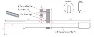
Here is my plan. I am starting to order parts now. The plan is based upon, of course, Colin's wonderful and inspirational project and directdrive's suggestion to use U-groove bearing. Thanks guys! And, last, it is also inspired by Clear Audio's arm.
My idea is let the track close to surface of record as much as possible.
Almost all the parts are pre-made. Two U groove bearings are 4x13x6 sealed.
Suggestions are welcome.
Attachments
Last edited:
two balls two bearings no carriage...
get a scale and weigh some bits and see. seems to me you just took simple and made it complex. just my observation. Best regards Moray James.
Two steel balls can be too much mass. It gets complicated and not diy friendly.
get a scale and weigh some bits and see. seems to me you just took simple and made it complex. just my observation. Best regards Moray James.
Niffy
Yes, I was thinking of your design when i made the comment. I do think that your arm is no less than smashing and it may well be that it is better than the original Cantus. It is all about balancing different design parameters and you have chosen a different one and done a fantastic job. I do not know exactly how important this parameter is but the Cantus have lost weight and size from the first revision and each step has proved to be an improvement in performance.
Moray
A V-track is a possibility but i thought that just two simple, low friction tubes or rods was easier. A shallow half round track would also work but on my Cantus i have tried a few different bearings including flanged and others that will not rely on a sliding action for vertical movement of the arm. The plain bearing that slides has always come out on top. From a theoretical standpoint i think that the friction from sliding adds some damping at and below the arm resonance.
super10018
Sorry if i was a bit unclear, i linked to a page that showed steel balls (balls of steel...) but my text says ceramic balls. The ceramic balls will add very little weight, less than 1g for each bearing. I agree that the balls are not very DIY for most but they can easily be ordered from a number of sources i guess.
Some thoughts
The inspiration for this idea has come from this thread and i really like the solution with a plain bearing rolling between two parallel rods/tubes, it is simple and it does away with the cutting of the glass tube i.e. very DIY friendly. What bothered me a bit was the less then well defined bearing/tube contact point with most bearings, hence the ball.
BR,
Anders
Yes, I was thinking of your design when i made the comment
. I do think that your arm is no less than smashing and it may well be that it is better than the original Cantus. It is all about balancing different design parameters and you have chosen a different one and done a fantastic job. I do not know exactly how important this parameter is but the Cantus have lost weight and size from the first revision and each step has proved to be an improvement in performance.Moray
A V-track is a possibility but i thought that just two simple, low friction tubes or rods was easier. A shallow half round track would also work but on my Cantus i have tried a few different bearings including flanged and others that will not rely on a sliding action for vertical movement of the arm. The plain bearing that slides has always come out on top. From a theoretical standpoint i think that the friction from sliding adds some damping at and below the arm resonance.
super10018
Sorry if i was a bit unclear, i linked to a page that showed steel balls (balls of steel...) but my text says ceramic balls. The ceramic balls will add very little weight, less than 1g for each bearing. I agree that the balls are not very DIY for most but they can easily be ordered from a number of sources i guess.
Some thoughts
The inspiration for this idea has come from this thread and i really like the solution with a plain bearing rolling between two parallel rods/tubes, it is simple and it does away with the cutting of the glass tube i.e. very DIY friendly. What bothered me a bit was the less then well defined bearing/tube contact point with most bearings, hence the ball
.BR,
Anders
Super,
As you get further through the thread the design changes alot. Namely going from a single tube 4 bearing to a 2 tube 2 bearing design with much thanks to pdr in his trials. To this day it has performed flawlessly and save for the odd swipe of the glass track with a dry qtip every two months or so it requires no maintenance.
Colin
As you get further through the thread the design changes alot. Namely going from a single tube 4 bearing to a 2 tube 2 bearing design with much thanks to pdr in his trials. To this day it has performed flawlessly and save for the odd swipe of the glass track with a dry qtip every two months or so it requires no maintenance
. Colin


Sorry if i was a bit unclear, i linked to a page that showed steel balls (balls of steel...) but my text says ceramic balls. The ceramic balls will add very little weight, less than 1g for each bearing. I agree that the balls are not very DIY for most but they can easily be ordered from a number of sources i guess.
Sorry, it is my mistake.
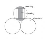
It is clever idea to put the bearing inside the ball. However, it will be simpler to just make a ring to fit out racer of bearing. See the drawing.
In Colin’s approach, his system is 4 points supporting system. Yours is 4 point supporting system too. The improvement I can see is the contact area. Yours is better. However, since Colin’s approach allows slight tolerance between bearings and shims, I can’t see how much improvement is.
I also don’t see the point to use two glass tubes because it is still 4 points supporting system. Colin’s design is much simpler and more effective.
In my plan, it is 2 points supporting system. So is Clear Audio's.
Attachments
- Home
- Source & Line
- Analogue Source
- DIY linear tonearm