As the vref, and impedance at that point, plays a critical role in the operation of this dac it would be interesting to know what the result of this mod and the reduced capacitance does to the DACs performance. Is resolution lost? Is there some frequency dependence introduced by an impedance that chances with frequency?
Soekris, could you comment? How low does the impedance here need to be to ensure the DACs performance capability is reached, and what effect will changes in impedance have?
As I said before, impedance on the vrefs need to be very low, as low as practical possible, from DC to Mhz.
This mod is meaningless until other people try it and comment on findings.
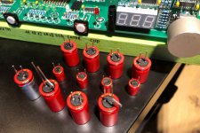
I did some more experiments today and I definitely like it better with BG NX 0.1uF cap in place. Without it the sound is a bit veiled, with it, more direct and detailed.
I also tried BG N 100/16 and BG N 47/50 caps: 100uF sounded a bit heavy weighted, with air and detail not that obvious. BG 47/50 sounded better and I had some hesitation which one to chose but in the end I stayed with original 10uF cap as the sound it produces is more "dramatic", with micro detail, air and presence pronounced very well; it's just so impressive right now.
Impedance on Vref is certainly important and someone still has to describe how it translates into perceived sound. What I described with my mods is simply the sound of a capacitor, which in my believe, has a certain sonic signature which affects the sound no matter where it is actually placed in a circuit.
Attachments
You make all of us green with envy, I have never seen so many BG all over in recent times ;-)This mod is meaningless until other people try it and comment on findings.
I did some more experiments today and I definitely like it better with BG NX 0.1uF cap in place. Without it the sound is a bit veiled, with it, more direct and detailed.
I also tried BG N 100/16 and BG N 47/50 caps: 100uF sounded a bit heavy weighted, with air and detail not that obvious. BG 47/50 sounded better and I had some hesitation which one to chose but in the end I stayed with original 10uF cap as the sound it produces is more "dramatic", with micro detail, air and presence pronounced very well; it's just so impressive right now.
Impedance on Vref is certainly important and someone still has to describe how it translates into perceived sound. What I described with my mods is simply the sound of a capacitor, which in my believe, has a certain sonic signature which affects the sound no matter where it is actually placed in a circuit.
You make all of us green with envy
Same here. My stash has shrunk into nothing where larger values are concerned

Attachments
Don't be alarmed. No one can pick that in a DBT against a normal hig quality cap with same ESR.
//
I will record this mantra and play it back on repeat while driving to make me feel better. Thank you.
Maybe this is a complete different topic, sorry then, but are these caps comparable to the decoupling caps in a 1541 ?
I am just looking into this article:
"Why decoupling is important, what really happens there ?
The process of musical signal creation inside the DAC is explained on this drawing of the TDA1540 guts. All elements are inside the IC but the capacitors CAN'T be integrated that's why they are outside. The switches take some current from each cap and build up the music signal.

TDA1541A decoupling and switches
As you can see, the caps are DIRECTLY responsible for music, for the sound , color and flavour.
"
Source: TDA1541A
Those caps where only 0.1uF...so maybe a dirfferent topic..but as there is no schematic or block diagram for the Soekris DAC one can only guestimate...
I am just looking into this article:
"Why decoupling is important, what really happens there ?
The process of musical signal creation inside the DAC is explained on this drawing of the TDA1540 guts. All elements are inside the IC but the capacitors CAN'T be integrated that's why they are outside. The switches take some current from each cap and build up the music signal.
TDA1541A decoupling and switches
As you can see, the caps are DIRECTLY responsible for music, for the sound , color and flavour.
"
Source: TDA1541A
Those caps where only 0.1uF...so maybe a dirfferent topic..but as there is no schematic or block diagram for the Soekris DAC one can only guestimate...
Last edited:
I don't think it is very similar. The decoupling caps clean up ripple in the current dividers at each step of division, while in the DAM, the caps help keep the reference voltage from which the MSB is directly derived. Kinda like keeping the current source in the 1540 clean.
It is important to remember that in the DAM there is a pretty good regulator for Vref already, and one that can be additionally improved with a pass transistor. As this regulator already has a pretty low output impedance at low frequencies, it can be argued that PD's solution using small but "good sounding" caps can work.
How low is the impedance of the regulator is impossible to tell without knowing the resistor values.
The opamp regulator should not be a problem at low frequencies anyway. It would be interesting if there is a solid proof that large capacitors are indeed needed.
Meanwhile i tested something else: my favourite JLSounds usb board vs the inbuilt Xmos.....
Having tried most of the available usb boards i was surprised to notice relatively small differences......
Interesting test. Among the boards you have tried are any using the new XU216 XMOS chip?
I found the 216 to be a noticeable step up over the XMOS 208. Agree that it’s worthwhile to power both sides of an isolated USB with a good PS rather than depend on the incoming USB 5V. Did you have issues with the handshake?
This mod is meaningless until other people try it and comment on findings.
I did some more experiments today and I definitely like it better with BG NX 0.1uF cap in place. Without it the sound is a bit veiled, with it, more direct and detailed.
I also tried BG N 100/16 and BG N 47/50 caps: 100uF sounded a bit heavy weighted, with air and detail not that obvious. BG 47/50 sounded better and I had some hesitation which one to chose but in the end I stayed with original 10uF cap as the sound it produces is more "dramatic", with micro detail, air and presence pronounced very well; it's just so impressive right now.
Impedance on Vref is certainly important and someone still has to describe how it translates into perceived sound. What I described with my mods is simply the sound of a capacitor, which in my believe, has a certain sonic signature which affects the sound no matter where it is actually placed in a circuit.
Mods similar to this are all over the dam1021 thread and indeed the improvements to microdetails are significant, especially with how the bass seems to peacefully coexist in a relaxing manner with the crispy highs with no single thing being muffled out, almost like a very airy open atmosphere. The idea is to bypass every shift register with a low value very low ESR cap.
You can do even better by throwing the series pass transistor in there and bypassing the 7x05 regulators completely instead using +-/5V for everything. Having different values in parallel will handle most things from high frequency transients to larger lower frequency spikes, in all there are about 4 different cap values on my vref, with a single larger cap at the start of the chain.
Essentially you end up with a high current very low impedance vref.
EDIT: While I realize the 19x1 has no 7x05 regulators, that is entirely my point, Soren removed them as no serious audio gear would ever throw them in places that ultimately end up in the output... and yes I totally get the point of the dam1021 being aimed at minimal effort DIY with its own regulation onboard, however the 19x1 didn't yet exist to please people like me.
Last edited:
This mod is meaningless until other people try it and comment on findings.
You mean people with a sizable stash of fat BG-Ns?
What people would love to know is whether simply removing the ceramics would lead to an improvement or not. Do you think you can throw any light on this?
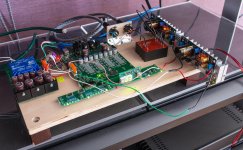
In other news i seem to have finally settled on a configuration which makes me happy. Or at the least finally does not make me crave the 1021.
Nothing fancy really.
1. PS board is used only for the +5v digital. The idea that those 78L/79L can power anything analogue or that a single transformer can be shared between analogue or digital is just absurd.
2. Shift registers are powered by 2 x Salas 1.3 and a smallish transformer. Gave up on the external PS with the 100,000uF and surprisingly the degradation was not so significant. For which - kudos to Salas

Power transformer will need an upgrade for deeper bass and solidity but even with a tiny 18VA the sound is very good. Current setting resistors are very audible and i use Caddock MP816 set for 200mA.
3. Output filter is removed
4. Output muting fets are removed. Surprisingly i cannot hear any pops these would have been masking, just improved low level resolution.
5. Not using an extra XMOS board anymore. The inbuilt XMOS solution is pretty good and currently matches the tonal balance slightly better. Besides i like the idea of a reduced number of disparate clocks in the chain.
And finally a question for Søren:
There must be an easy way to apply external power in place of the usb +5v. What is the best place to do this? L3?
Attachments
And finally a question for Søren:
There must be an easy way to apply external power in place of the usb +5v. What is the best place to do this? L3?
L3 goes from the USB plug to xmos regulators, so it's a good place to do it. Please note that the USB side of L3 also supply +5V to the USB protection part.
4. Output muting fets are removed. Surprisingly i cannot hear any pops these would have been masking, just improved low level resolution.
I felt this improved things on the 1021 also. The only plops are during poweron/poweroff which is easily masked with a relay NC shunt with poweron delay and instant poweroff NC which worked absolutely amazing. There isn't any need to mute during samplerate change unlike in the old days of the dam1021.
Hmm interesting I think I want to try removing them but as my eyesight is surprisingly bad can anyone please mark where the muting FETs are located please.4. Output muting fets are removed. Surprisingly i cannot hear any pops these would have been masking, just improved low level resolution.
.
What people would love to know is whether simply removing the ceramics would lead to an improvement or not. Do you think you can throw any light on this?
I talked about it already here: dam1941 - Next Gen Discrete R-2R Sign Magnitude 24 bit 384 Khz DAC module
However, I will do a bit more and test again the effect of these caps. I made them into nice modules which can plug quickly into sockets and this way I can do more comparisons. What's interesting, the sets don't measure the same: out of four, two show 2uF combined capacitance, one shows 4uF and one is 6uF. And I didn't mixed them up, since right after desoldering I placed them in a proper order on a sticky tape. Could that be an issue with assembly providers? My board has a serial# 0010
Attachments
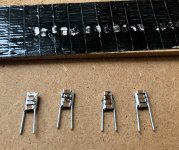
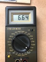
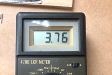
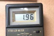
I have to apologize for posting that info on capacitance mismatch. It came out that two caps in my ‘modules’ where somehow damaged and where showing close to zero resistance, those were the ones with 2uF capacitance. I could’ve damaged them while soldering or maybe by placing in a vise.
- Home
- Vendor's Bazaar
- dam1941 - Next Gen Discrete R-2R Sign Magnitude 24 bit 384 Khz DAC module