I would not want to mess with the mounting clips and the thermal pads at the same time. If the thermal pad is misaligned, you're in for trouble. There aren't many thermal pads that fit the LM3886T well, though you can buy sheets of thermal pad and cut your own. I think most would probably prefer to use the LM3886TF and be done rather than having to spend $30-40 on a large sheet of thermal pad.
There are many valid solutions. Some of these solutions are virtually fool-proof and others aren't. I sell hundreds of boards each year and need those builds to have the highest probability of success. I need to provide a solid solution, and eliminating the mounting hassles of the LM3886T is just fundamental risk management.
Now, this is DIY, so some will colour outside of the lines. That's to be expected and is part of the fun. I will certainly provide the part numbers for the thermal pad and shoulder washers needed for the LM3886T in the design doc. But that will be an "advanced" option. Proceed at your own risk and expense.
This discussion is really only relevant for those who want to use a ±36 V regulated supply. For those using a linear supply, such as my Power-86 with a 2x25 VAC transformer (Antek AN-5225) or 2x24 VAC transformer (Hammond 1182S24) it is a moot point as the rail droop at higher output power will reduce the thermal dissipation in the LM3886es to the point where there will be no difference in performance between them.
I think my recommendations will be (subject to change):
Tom
There are many valid solutions. Some of these solutions are virtually fool-proof and others aren't. I sell hundreds of boards each year and need those builds to have the highest probability of success. I need to provide a solid solution, and eliminating the mounting hassles of the LM3886T is just fundamental risk management.
Now, this is DIY, so some will colour outside of the lines. That's to be expected and is part of the fun. I will certainly provide the part numbers for the thermal pad and shoulder washers needed for the LM3886T in the design doc. But that will be an "advanced" option. Proceed at your own risk and expense.
This discussion is really only relevant for those who want to use a ±36 V regulated supply. For those using a linear supply, such as my Power-86 with a 2x25 VAC transformer (Antek AN-5225) or 2x24 VAC transformer (Hammond 1182S24) it is a moot point as the rail droop at higher output power will reduce the thermal dissipation in the LM3886es to the point where there will be no difference in performance between them.
I think my recommendations will be (subject to change):
- Regulated supplies, including SMPSes: ±36 V (220 W; 8 Ω) or ±28 V (150 W; 8 Ω).
- Unregulated supplies: Power-86 with 2x24 VAC or 2x25 VAC power transformer (350-500 VA).
- Use the LM3886TF.
Tom
So if I upgrade my Trafos for my 286 conversion project to 500va ones, while keeping my 3U (0.41k/w) chassis with the already built in Pwr86, what voltage should I choose?
The 2x25 or the more conservative 2x24? What output power would I get with 2x24 into 8ohms/4ohms?
BTW: Good Choice using the TF version for all the above reasons
The 2x25 or the more conservative 2x24? What output power would I get with 2x24 into 8ohms/4ohms?
BTW: Good Choice using the TF version for all the above reasons
2x25 VAC and 2x24 VAC are both good choices. Get 2x25 VAC if you can. If not, get 2x24 VAC. 2x24 VAC seems to be more commonly available from the various transformer manufacturers.
I mentioned the Hammond transformer as it is available world-wide from Mouser (Hammond P/N: 1182S24; Mouser P/N: 546-1182S24), unlike the Antek AN-5225, which realistically is US-only (or at least North America-only) due to the cost of shipping. Another transformer candidate available in North America is the Triad Magnetics P/N: VPT48-10400. It's available from Digikey (P/N: 237-1358-ND) but is rather pricey.
Those with 230 V mains voltage may find the Multicomp P/N: VTX-146-500-125 (2x25 VAC, 500 VA, 230 VAC primary) useful. It's available from Farnell in the EU.
RS Components P/N: 123-4040 (2x25 VAC @ 500 VA, 115/230 VAC primary) would be a good candidate as well.
RS Components P/N: 123-4031 (2x25 VAC @ 500 VA, 230 VAC primary) looks like a nice potted transformer.
RS Components P/N: 117-6071 (2x24 VAC @ 500 VA, 115/230 VAC primary) would also be suitable.
Tom
Last edited:
Thx.
I can get both quite easily. So far I’ve used the Amplimo brand type transformers mainly shipping from the Netherlands.
However the reason for my above question was rather if a 2x24v would buy me some leeway for the thermal limit when only using the Modushop 3U instead of the 4U and if yes, by how much. Of course at the expense of the total power output. I could easily just use 200w into 8ohms instead of the 220, but I am not sure about the math and I am also not sure if that would really reduce significantly the thermal dissipation by much.
Just for info: the toroidy transformers from Poland are a good option in Europe. They have different ranges. Their audio range 500VA are only 75€ and are a really good value. TTSA0500 - Transformer AUDIO TSA500VA - voltage to 50 V - Shop Toroidy.pl
However the reason for my above question was rather if a 2x24v would buy me some leeway for the thermal limit when only using the Modushop 3U instead of the 4U and if yes, by how much. Of course at the expense of the total power output.
As mentioned in Post #29:
Math says:
Ambient temp: 25 ºC
Max. heat sink temp: 60 ºC
Supply voltage: ±35 V
Crest factor, music: 14 dB
8 Ω, sine wave: 0.32 K/W
8 Ω, music: 0.46 K/W
4 Ω, sine wave: 0.17 K/W
4 Ω, music: 0.25 K/W
Adding to that:
Ambient temp: 25 ºC
Max. heat sink temp: 60 ºC
Supply voltage: ±28 V
Crest factor, music: 14 dB
8 Ω, sine wave: 0.49 K/W
8 Ω, music: 0.71 K/W
4 Ω, sine wave: 0.26 K/W
4 Ω, music: 0.39 K/W
I'd expect 150 W with ±28 V and 220 W with ±35 V, if using regulated supplies. Maybe more like 125 W with ±28 V and 175 W with ±35 V if using linear unregulated supplies.
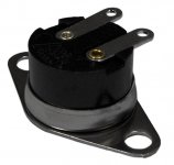
The 3U Modushop Dissipante heat sinks are rated at 0.41 K/W. The 4U is rated at 0.31 K/W. Thus, if you want to squeeze the amp into a 3U chassis, I suggest lowering the supply voltage to ±28 V. Alternatively, you could put a thermal switch on the heat sink that turns the amp off if the heat sink temperature exceeds 60-65 ºC. Something like Mouser P/N: 785-3004-00190011 would work. See attached image.
I could easily just use 200w into 8ohms instead of the 220, but I am not sure about the math and I am also not sure if that would really reduce significantly the thermal dissipation by much.
24 VAC vs 25 VAC is a bit like picking gnats.
Tom
Attachments
Last edited:
A question I have from a long time, is there any Sonic advantages of using SMD components instead of through hole?
Good question. Thanks for asking.
SMD components have many advantages, including:
- The best performing opamps are now all SMD-only.
- Precision SMD resistors are available in tight tolerances at affordable prices.
- SMD components allow for a tighter PCB layout, resulting in fewer paracitics, and better performance.
- SMD components allow for a smaller PCB layout, which means lower cost.
- When properly chosen, SMD builds will perform at least as good or better as thru-hole builds.
Not all SMD components (specifically resistors and capacitors) are created equal. For the lowest THD (best performance), resistors with low temperature and voltage coefficients must be chosen. Also capacitor dielectrics matter and must be chosen carefully if you want the circuit to perform well.
The good news is that I take care of all those details for you so you can build a high-performing amp.
My SMD-based amps perform measurably better than my thru-hole amps. Most of the difference is due to the availability of better parts in SMD.
Unfortunately, I don't have 250 volunteer participants to participate in a scientifically valid study to determine whether an SMD-based amp sounds better than a thru-hole design. Measurements indicate that my SMD-based amps should sound as good or better than thru-hole designs. That is also my own subjective experience, but I can easily be accused of bias.
Considering that the availability of leaded parts is dwindling by the day and the performance you can get with SMD parts, I think reversing your question makes more sense: "Why would you build anything using leaded components?"
Tom
Modulus-686: 380W (4Ω); 220W (8Ω) Balanced Composite Power Amp with extremely low THD
Tom, I can say that temperature coefficient definitely effects sonic quality. This is one of the things discovered when a late reviewer hear something was different between builds. My speculation is the nature of the material used to produce lower temperature coefficient resistors, I am sure it is true with other measurable characteristics as well.
It is also important to rely on component suppliers to maintain the same source of raw material and process in order to maintain the same sonic qualities. Some manufacturers will start looking for lower cost material sources which they think maintains the same measured performance. However, it may not maintain same audio sound characteristics.
Last edited:
Tom, I can say that temperature coefficient definitely effects sonic quality.
The temperature coefficient of a resistor will definitely impact the performance of a circuit if significant heat is dissipated in the resistor. The instantaneous power dissipated in the resistor heats up the resistor and causes it to change resistance. This introduces a signal-dependent change in the output signal = distortion.
In an audio amp, the obvious culprit for this effect is the feedback resistor(s).
Yep. I did think through this and designed the MOD686 accordingly. You can get low TC resistors in SMD and you can size them such that they won't heat up much.
Tom
Thanks for your detailed reply.Good question. Thanks for asking.
SMD components have many advantages, including:
- The best performing opamps are now all SMD-only.
- Precision SMD resistors are available in tight tolerances at affordable prices.
- SMD components allow for a tighter PCB layout, resulting in fewer paracitics, and better performance.
- SMD components allow for a smaller PCB layout, which means lower cost.
- When properly chosen, SMD builds will perform at least as good or better as thru-hole builds.
Not all SMD components (specifically resistors and capacitors) are created equal. For the lowest THD (best performance), resistors with low temperature and voltage coefficients must be chosen. Also capacitor dielectrics matter and must be chosen carefully if you want the circuit to perform well.
The good news is that I take care of all those details for you so you can build a high-performing amp.
My SMD-based amps perform measurably better than my thru-hole amps. Most of the difference is due to the availability of better parts in SMD.
Unfortunately, I don't have 250 volunteer participants to participate in a scientifically valid study to determine whether an SMD-based amp sounds better than a thru-hole design. Measurements indicate that my SMD-based amps should sound as good or better than thru-hole designs. That is also my own subjective experience, but I can easily be accused of bias.
Considering that the availability of leaded parts is dwindling by the day and the performance you can get with SMD parts, I think reversing your question makes more sense: "Why would you build anything using leaded components?"
Tom
As you said, it makes sense to go for SMD which has Sonic advantages, my only intention of such question was, I see now a days even in DIY people are moving towards SMD which makes assembly and troubleshooting difficult in case of issues later on. In your case anyone shouldn't have such issues as you are providing assembled boards.
All the best, will keep an eye on this thread and hope to build this amp in future.
Regards
Bilal
As you said, it makes sense to go for SMD which has Sonic advantages, my only intention of such question was, I see now a days even in DIY people are moving towards SMD which makes assembly and troubleshooting difficult in case of issues later on. In your case anyone shouldn't have such issues as you are providing assembled boards.
I understand completely.
From a technical perspective (measured performance, parts availability) and business perspective (cost, in particular the cost of assembly) SMD wins hands down. I do agree with your observations regarding DIY and rework. There's no doubt that SMD makes DIY more difficult, which in part is why I decided on offering only pre-built boards (no bare boards). It wasn't a decision I took lightly as I do want to keep DIY going, but I am convinced it was the right decision. Time will tell.
At the performance levels I'm operating at, the assembly needs to be done by the book to be successful and provide the promised performance.
Tom
FedEx delivered the PCBs almost a full week ahead of schedule. Love FedEx.
Now the boards will go off to assembly. That's expected to take about 20 business days (so almost a month!). Pardon the delay. I'm confident it'll be worth the wait.
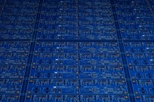
I must say that I rather like the blue-on-gold colour scheme. While it is pretty, the gold plating was not chosen for aesthetics. The gold is easier for the assembly folks to work with. It also makes the boards ROHS compatible.
Tom
Now the boards will go off to assembly. That's expected to take about 20 business days (so almost a month!). Pardon the delay. I'm confident it'll be worth the wait.
I must say that I rather like the blue-on-gold colour scheme. While it is pretty, the gold plating was not chosen for aesthetics. The gold is easier for the assembly folks to work with. It also makes the boards ROHS compatible.
Tom
Attachments
I use ENIG, which is a chemical process of gold plating that forms a thin layer of gold on the copper of the PCB. I'm not aware of anything called "chemical gold". Gold is gold and there's enough of it on the pads to prevent surface contamination and ensure a good solder bond. That's the point of it.
I don't know if the gold is on the traces or just on the pads. You wouldn't need the gold on the traces, so it would seem like a very reasonable cost reduction to dunk the boards in the gold plating soup after the solder mask has been applied and only get gold on the traces. I imagine that soup is pretty expensive.
I'm not aware of anyone who is depositing gold onto circuit boards through sputtering or the like. It'd be an annoying process as gold doesn't want to stick to anything. In semiconductor manufacturing, an adhesion layer of chromium is commonly used to make the gold stick to the aluminum pads on the IC. Fancier layer stack-ups are pretty common too.
Tom
Last edited:
Expanding on what Tom said, ENIG is a very thin chemically-applied plating to prevent oxidation of the pads. The gold is very real but it's not robust as a traditional gold-over-nickel-over-copper (not chromium). These days you only see that selectively applied to edge connector fingers. Solder mask these days is almost always SMOBC (solder mask over bare copper), so I doubt you'll find gold on the non-exposed copper, though you're free to carefully scrape the solder mask and look for yourself.
Solder mask these days is almost always SMOBC (solder mask over bare copper), so I doubt you'll find gold on the non-exposed copper, though you're free to carefully scrape the solder mask and look for yourself.
Or ask your PCB manufacturer what their process is.
") Given that the gold is not needed on the traces, I highly doubt there is any gold on the traces. Less gold -> lower cost.
Given that the gold is not needed on the traces, I highly doubt there is any gold on the traces. Less gold -> lower cost.There is another plating process out there that involves a fancier layer-stack. Electroless Nickel, Electroless Palladium, Immersion Gold (ENEPIG). So the same as ENIG but with palladium added between the nickel and gold layers.
For those interested in reading more about gold plating of PCBs, there's a ton of information available here: PWB Processes: ENEPIG nickel-free PCB coating
Gold fingers for edge connectors came to mind for me as well. Even for those, the gold layer is often only 300 micro-inches (gotta love the metric-imperial mix/match units) or 7-8 µm thick.
Tom
Last edited:
Modulus-686: 380W (4Ω); 220W (8Ω) Balanced Composite Power Amp with extremely low THD
I like the fact that only the pads being plated. I guess I need to check into this a bit more since we see lots of different plating on audio connectors, some stand up to corrosion well, some not so much. But technically for pc boards with soldering work, we only want the minimum necessary to improve boning of the soldering joints.
For some reason, the gold plating nowadays just don’t look like real gold.
Last edited:
For some reason, the gold plating nowadays just don’t look like real gold.
That may be caused by the thickness of the gold layer. I suppose the surface finish (think roughness) could play in as well.
Tom
- Home
- Vendor's Bazaar
- Modulus-686: 380W (4Ω); 220W (8Ω) Balanced Composite Power Amp with extremely low THD