Hi,
read all posts about L7, L12-2, L15 / L150(W), L20-5 and I need some help to understand which of those are the best for time being? I mean which sounds better (not measures better).
Or which one would fit my burnt Denon PMA-510ae which I bought on ebay and now de-soldered one channel output darlingtons, and idle adj transistor sitting on heatsink. All 3 are totally shorted between all legs.
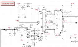
Now I'm thinking is there are any point to restore original circuit as reviews for those lower models (PMA-5x0ae) are not great... Circuit for reference attached.
Luckily by searching ebay I found still available L7 MOSFET which all assembled one channel will be cheaper by half for BOM of restoring all drivers, outputs, diodes, zenners that are currently blown up.
So I'm scratching head which of LJM would be valid fit into Denon? Not sure why but I'm more looking at something on MOSFETS... Like L7, but L20 measurements looks great as well...
Anyway, which sounds better?
Thanks.
read all posts about L7, L12-2, L15 / L150(W), L20-5 and I need some help to understand which of those are the best for time being? I mean which sounds better (not measures better).
Or which one would fit my burnt Denon PMA-510ae which I bought on ebay and now de-soldered one channel output darlingtons, and idle adj transistor sitting on heatsink. All 3 are totally shorted between all legs.
Now I'm thinking is there are any point to restore original circuit as reviews for those lower models (PMA-5x0ae) are not great... Circuit for reference attached.
Luckily by searching ebay I found still available L7 MOSFET which all assembled one channel will be cheaper by half for BOM of restoring all drivers, outputs, diodes, zenners that are currently blown up.
So I'm scratching head which of LJM would be valid fit into Denon? Not sure why but I'm more looking at something on MOSFETS... Like L7, but L20 measurements looks great as well...
Anyway, which sounds better?
Thanks.
Attachments
That is a tough question. When LJM introduced the L20.5 he said he thinks/hopes it is the best yet.
Some people really like the MX50SE.
Some people the L12-2.
I am currently quite enjoying the LJM QUAD405-2 with gain modification, current source mod (my own) and OPA228 op amp.
So perhaps you should refine with the following:
1. What is your level of electronics expertise?
2. If you want to go with an LJM module which fits your chassis and heatsink?
3. What fits the voltage, power and current needs? (Speaker impedance and output power.)
The L20.5 & L12-2 mount quite differently to the heatsinks (and have a different size/shape/form factor) than the L20SE or the LJM QUAD405-2, for example.
If you are an expert then perhaps L20.5 or L12-2. But I can't tell you if you would prefer the sound of the L7, L15 or the QUAD405-2.
If you have heard a nicely modified/restored QUAD (and you liked it) then maybe you would like the QUAD405-2. But perhaps that needs more electronics experience and the expectation to do some modifications.
If you are a beginner then I might suggest the L20SE which offers the key features of the main LJM designs (blameless style amplifier) but is simpler and easier to build. Yet the L20SE has some ruggedness due to the type of output transistors used and the use of two pairs.
It also depends on the budget. You can get L20 V10 already assembled and mounted on aluminum angles which can help with installation depending on your chassis and heatsink.
If you really like the sound of the Denon then you might want to stick with that if you can get parts.
Last edited:
Sure. I followed the DESMITH website with some modifications.
The site is: Quad 405-2 upgrades
Note that I am using the LJM QUAD405-2 boards. Those come with TL071.
My first modification was the gain reduction exactly as on that site EXCEPT I did not change C2. I did put a 47uF 50V UES cap in that place but that is likely quite unnecessary. I had it leftover from something else and used it. I also bypassed the UES with 0.1uF PP film. I can't really comment on whether that is necessary or not. So LJM C4 goes from 47n to 150n. Next LJM R6 goes from 330k to 100k (I paralleled with 150k on the back for the same result).
My second modification was to remove the TL071, install a machine socket and solder 0.1uF PP film and Panasonic "M" series 47uF 63V from directly on the socket supply pins to the ground plane. (The input ground plane near the op-amp.)
Then I installed an OPA228 op-amp. (Actually I tried RC5534/NE5534 first before I found the nice OPA228 left over from a test and measurement project.)
Next I did a modification of the current source modification. I added an additional/new BC556 that I put it in the spot of the 470 Ohm resistor [LJM R14] that I removed. The 100 Ohm [LJM R15] was changed to 220 Ohms and the base of the added BC556 was connected to one leg of the 220 Ohm resistor.
I did not remove the bypass capacitor [LJM C5] of the current source. I left the original bypass installed. Instead of removing C5 I would leave it and add a 0.1uF PP if one is worried about C5...
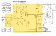
Here is my own "new" current source mod that I have not found online for QUAD405: An important addition to the current source mod (in my opinion) is to split the 22k current source resistor [LJM R13] into a 12k and series 10k in the place of the 22k. Then in the middle where those two join I bypassed with a large (470uF low ESR switching supply capacitor) to the positive rail. This is to remove the power supply ripple and noise from the current source. [Why do I think this change is important? I expect the bypassing to be far more effective at a higher impedance point. Please read the section around "If R1 and R2 are replaced with a single 100 ohm resistor (omitting C2), ripple rejection falls to 25dB (82mV RMS ripple)." on the following ESP link under figure 5: Small Power Supplies]
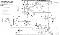
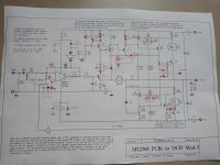
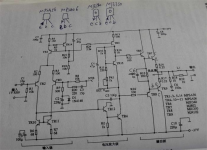
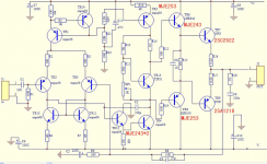
The added transistor is in the location shown in the attached schematic. [The first attached blurry schematic. The second schematic is the LJM stock schematic.] However the rest does not follow the schematic. For example I left the bypass capacitor that came on the LJM board for the current source.
I also soldered 1000uF bypasses from the underside of the fast-on tabs to the POWER ground plan under the board. I also add two film (PP) bypasses in the same location.
Unfortunately I have not made a schematic or photos of the final set of changes. If this is hard to follow let me know. It is assembled but I can try to take some photos.
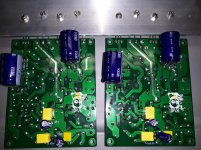
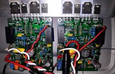
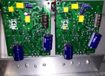
The attached older photos are from halfway through the mods. The installed op amp is RC5534 in the picture (NE5534). And the pictures are before the current source modifications.
To be clear I do think the LJM QUAD405-2 is very good as delivered. It is just my hobby to make it as good as I can.
The site is: Quad 405-2 upgrades
Note that I am using the LJM QUAD405-2 boards. Those come with TL071.
My first modification was the gain reduction exactly as on that site EXCEPT I did not change C2. I did put a 47uF 50V UES cap in that place but that is likely quite unnecessary. I had it leftover from something else and used it. I also bypassed the UES with 0.1uF PP film. I can't really comment on whether that is necessary or not. So LJM C4 goes from 47n to 150n. Next LJM R6 goes from 330k to 100k (I paralleled with 150k on the back for the same result).
My second modification was to remove the TL071, install a machine socket and solder 0.1uF PP film and Panasonic "M" series 47uF 63V from directly on the socket supply pins to the ground plane. (The input ground plane near the op-amp.)
Then I installed an OPA228 op-amp. (Actually I tried RC5534/NE5534 first before I found the nice OPA228 left over from a test and measurement project.)
Next I did a modification of the current source modification. I added an additional/new BC556 that I put it in the spot of the 470 Ohm resistor [LJM R14] that I removed. The 100 Ohm [LJM R15] was changed to 220 Ohms and the base of the added BC556 was connected to one leg of the 220 Ohm resistor.
I did not remove the bypass capacitor [LJM C5] of the current source. I left the original bypass installed. Instead of removing C5 I would leave it and add a 0.1uF PP if one is worried about C5...
Here is my own "new" current source mod that I have not found online for QUAD405: An important addition to the current source mod (in my opinion) is to split the 22k current source resistor [LJM R13] into a 12k and series 10k in the place of the 22k. Then in the middle where those two join I bypassed with a large (470uF low ESR switching supply capacitor) to the positive rail. This is to remove the power supply ripple and noise from the current source. [Why do I think this change is important? I expect the bypassing to be far more effective at a higher impedance point. Please read the section around "If R1 and R2 are replaced with a single 100 ohm resistor (omitting C2), ripple rejection falls to 25dB (82mV RMS ripple)." on the following ESP link under figure 5: Small Power Supplies]
The added transistor is in the location shown in the attached schematic. [The first attached blurry schematic. The second schematic is the LJM stock schematic.] However the rest does not follow the schematic. For example I left the bypass capacitor that came on the LJM board for the current source.
I also soldered 1000uF bypasses from the underside of the fast-on tabs to the POWER ground plan under the board. I also add two film (PP) bypasses in the same location.
Unfortunately I have not made a schematic or photos of the final set of changes. If this is hard to follow let me know. It is assembled but I can try to take some photos.
The attached older photos are from halfway through the mods. The installed op amp is RC5534 in the picture (NE5534). And the pictures are before the current source modifications.
To be clear I do think the LJM QUAD405-2 is very good as delivered. It is just my hobby to make it as good as I can.
Attachments
Last edited:
Thanks a lot for your reply.
I know the stock schematics very well as I posted it myself.
I did some Snook's mods.
~ QUAD 405-2 Amplifier Modification and Information ~
I followed his dcd-3 mods but let tl071 in place because I didn't have suitable single op-amp.
I suspect noise coming from those cheap little guys or the proximity with the Smps500r I used.
Attachments
Thanks Kozard for a response.
Actually I have measured available surface of heatsink for new boards and have available 3 choices left: L7, MX50SE, MX50X2.
It was complains that L7 sounds not very good at lower volumes, which is most important thing for me, as I'm listening music most of the time at reasonably quiet and comfortable level, within 1W range. Only 4 times in a year I need from amplifier 25w-50w per channel.
Connected to bookshelf speakers Triangle Titus ES. 8ohm nominal (4ohm drop in resonance freq). 60W nominal, max peak 120w.
kesrmk,
I never heard an L7 because I read a lot of trouble with some L series but I use both mx50x2 and mx50se.
Those 2 boards sounds good to my hear.
After listening both a lot I think I prefer mx50x2.
Mx50se is very good though and probably measure better but I found it a bit lifeless with my system.
The 402-2 boards impressed me alot with their bodyed sound but as said before I got a hiss problem with them.
I listen music most of the time under 1w on a pair of elipson p4i (93db@1w@1m).
Honestly I think both can do great music and perhaps your taste are not the same as other people.
It's hard to tell which board you'll prefer on your system.
The 402-2 boards impressed me alot with their bodyed sound but as said before I got a hiss problem with them.
I use a regular transformer, bridge and cap supply with my QUAD405-2 and mine are silent. No hiss. I never tried it with my SMPS supply.
Even before the gain modification I don't recall any hiss.
Thanks Kozard for a response.
Actually I have measured available surface of heatsink for new boards and have available 3 choices left: L7, MX50SE, MX50X2.
It was complains that L7 sounds not very good at lower volumes, which is most important thing for me, as I'm listening music most of the time at reasonably quiet and comfortable level, within 1W range. Only 4 times in a year I need from amplifier 25w-50w per channel.
Connected to bookshelf speakers Triangle Titus ES. 8ohm nominal (4ohm drop in resonance freq). 60W nominal, max peak 120w.
I like my MX50SE also, but with only one output pair I use a lower voltage supply with that since my speakers are 4 Ohms (actual measured 4 Ohms, measured with REW.)
I would likely have bought L20SE instead (if I knew it existing) instead of the MX50SE.
I also have the MX50x2 however mine is modified with genuine Toshiba drivers and outputs since the stock device blew at +/- 50V first power up on one of the boards. No problems after rebuilding with genuine Toshiba drivers and outputs.
I think the MX50SE, MX50X2 and L20SE are all pretty nice. However it is my view that one pair of D1047/B817 has marginal SOA for 4 Ohm speakers.
So would suggest L20SE if it fits the heatsink (much larger SOA output transistors and two pairs).
But all are good if you don't exceed the real SOA. (Be aware that specs can be fairly "optimistic".)
The QUAD405-2 is what I call fairly advanced and quite impressive. But if you have not done this before I would suggest a simpler starting point. I think MX50SE and L20SE are simpler to start with. There are aspects of the MX50X2 (especially the lower two outputs and the diodes) that are a notch above beginner.
Honestly I think both can do great music and perhaps your taste are not the same as other people.
It's hard to tell which board you'll prefer on your system.
This is key.
Without knowing what sort of amps you really like it is hard to know what you will enjoy.
But at least you know that there are multiple confirmations or endorsements out there for the MX50SE, MX50X2, QUAD405-2, etc.
Be aware that this is quite a rabbit hole. There are lots of nice amplifiers. Like KSA50... Maybe APEX FH9. MA-9S2. (Endless actually.)
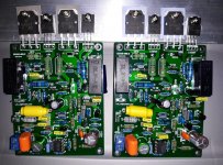
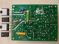
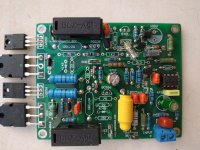
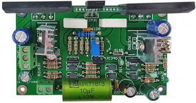
Another nice one that is quite similar to many LJM designs (which are basically Blameless type except VAS) is pictured. But this one has two transistors in the VAS. I quite like my pair.
I found it on AliExpress under the same "Ghxamp HIFI Classic Discrete Amplifier Board Audio AMP 35V/us By "Audio Power Design Manual" 2SC2922 Dual 24V-Dual 50V 1Pairs"
Ghxamp HIFI Classic Discrete Amplifier Board Audio AMP 35V/us By "Audio Power Design Manual" 2SC2922 Dual 24V Dual 50V 1Pairs|amplifier board|audio ampamp designer - AliExpress
I am planning to try various VAS mods on some of my LJM designs. I am just busy with the QUAD405-2 recently and a couple DAC projects.
Attachments
Thanks a lot for your reply.
I know the stock schematics very well as I posted it myself.
I did some Snook's mods.
~ QUAD 405-2 Amplifier Modification and Information ~
I followed his dcd-3 mods but let tl071 in place because I didn't have suitable single op-amp.
I suspect noise coming from those cheap little guys or the proximity with the Smps500r I used.
That is a lot of changes. Did you do them one by one and check performance between steps?
I suspect the hiss is not the TL071 because I don't recall any hiss with the stock LJM QUAD405-2 which arrived with the TL071. Or with the RC5534, NE5534 or OPA228. Especially since you have done the gain reduction mod already.
I also suspect the hiss is nothing to do with the removal of the current limiters/SOA networks. (I have not done that. Did you do each change one by one? If so, did you notice a difference after removing the SOA circuit? If so, what did you notice? I was thinking of either leaving the networks there or just decreasing the sense resistor value after installing bigger outputs such as 2SC5200 or 2SC6145. Since I have 4 Ohm speakers I was thinking of installing the higher current/SOA outputs and then halving the current sense resistor values (R35 & R36).)
So I would guess possible sources of the problem would be:
1. The SMPS
2. The current source modifications
3. I really don't know about the inverting vs non-inverting change. I have not tried that.
Do you have a regular (trans/bridge/cap) supply that you can try? That might be a fairly easy test to eliminate a possibility.
It really is a guess but I wonder if the current source modifications could be the cause. I didn't like the idea of removing C5 (so I didn't) because how else do you filter out the power supply noise and ripple from the current source? Why "program" or set the current source value with a noisy signal (the power supply voltage)?
Can you quickly try putting C5 back? Perhaps with a 0.1uF PP film in parallel also? (That is pretty quick and easy.) If that reduces the hiss then I suggest splitting R13 (22k) into series 12k and 10k and then bypass from the junction of the series 12k and 10k to the +ve supply rail with a good capacitor (maybe 470uF low ESR) to further filter out noise. Since your SMPS has high frequency noise I suggest you use a 470uF low ESR high frequency type intended for switching supplies. (Good ESR at 100kHz.)
Programming the current source with a noisy signal (the power supply voltage across R13) might be important in conjunction with your SMPS. So the hiss problem might be a combination of that current source changes (which included removing C5) and the SMPS.
Those are my best guesses right now.
Last edited:
Hi,
in terms of what type of amplifier I like or prefer...
I have repaired (so had chance to listen) short list of SS amplifiers, and from those I like:
1. Yamaha AX-400 (currently using). It has triple EF output stage (where emiters for stages are not connected together) and I really enjoy transparent undistorted sound with feel of no lack of current in driving my speakers. So it is clear transparent powerful and not harsh in hi frq.
2. Marantz PM-80mkII, it was my main amplifier for 10 years before I got Yamaha. What I do like in Marantz - very dynamic and super strong and deep - "tasty" bass. Never heard such attractive solid and strong and tasty bass in any amps I had. p.s. it has Class A mode, which adds to the sound proper "class A", but need to modify a bit idle circuit, as it comes from factory biased too cold, not enough travel for pot, to set mA as defined in service manual. Disadvantage of Marantz - it does not have effect of "transparency", somehow it is too "soft" at upper mids and hi freq.
Amps I had and dislike:
1. Rotel RA-921 - dry muddled sound. No wonder for cheapest model in the line. They even didn't added speaker protection, so you will hear pops when turning on amplifier.
2. Just compared one channel for my Denon PMA-510ae - much less transparency than Yamaha AX-400. But better than Rotel. So not interesting at all.
3. Technics receiver SA-200L - sound focused on low frequencies, very heavy sound, boomy, could be good only for playing in parties/clubs.
But most of all like like my valve amps. Have few, tried to solder by myself approx 10 with different valves and different circuitry (SE, PP) all recalculated by myself based on valves used.
1. my main valve amplifier is PP EL34/6L6/KT66 in UL with 6H23P (E88CC/6DJ8) driver connected without phase splitter. Instead used CC source for both cathodes for output tubes so 2nd tube is fed by cathode. Output transformers oversized up to 280W.
2. my second valve amp is tiny triode in PP 6N6P ( ECC99/E182CC) driven by 6H23P. Proper triode as output adds charm to the sound. Phase splitter is rarely used "paraphase"
type.
I can tell I like PP circuitry more than SE. Something in SE does not fits to my ears... Can't keep listen to SE apms for extensive time... After 1 hour I must turn it off. Meanwhile it is not the case with PP amps.
Anyway, I'm leaning to try MX50SE CFP Sziklai connection out of curiosity...
If I will not like it, then will modify output stage to something traditional.
Quad or L6-E210 unfortunately are not for my limited in size heatsink...
Thanks for advices!
Last edited:
I did some Snook's mods.
~ QUAD 405-2 Amplifier Modification and Information ~
I followed his dcd-3 mods but let tl071 in place because I didn't have suitable single op-amp.
I took a couple of photos of the current configuration. I like the gain mod and the op-amp swap (OPA228).
I will need to spend more time with it to decide on whether I keep this particular set of current source modifications or not.
Attachments
Member
Joined 2003
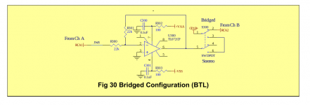
Stupid question - I have a handful of L15D-Pro modules that I've been using for the past few years. I would like to repurpose them, wondering if there will be any issue by simply inverting signal input to one module, then wiring the output of the pair of amps for bridge mode operation?
Member
Joined 2003
Yes, Assuming that the L15D is meant for 4 ohm min load, the bridged operation would need to be connected to 8 ohm load. The reference IRAUDAMP7 document indicates that bridge mode is possible, any I don't see anything obvious that would prevent it so I am hopeful.
I was hoping to simply use a basic inverting buffer stage with an op-amp on one channel for use with unbalanced signal. Alternatively I do have some equipment with balanced XLR output that I could split the balanced signal across the pair of amps.
I was hoping to simply use a basic inverting buffer stage with an op-amp on one channel for use with unbalanced signal. Alternatively I do have some equipment with balanced XLR output that I could split the balanced signal across the pair of amps.
Attachments
Last edited:
Yes, Assuming that the L15D is meant for 4 ohm min load, the bridged operation would need to be connected to 8 ohm load. The reference IRAUDAMP7 document indicates that bridge mode is possible, any I don't see anything obvious that would prevent it so I am hopeful.
I was hoping to simply use a basic inverting buffer stage with an op-amp on one channel for use with unbalanced signal. Alternatively I do have some equipment with balanced XLR output that I could split the balanced signal across the pair of amps.
I’ve actually used such an inverting buffer stage on my L15D boards for SE inputs. I used something called a "inverting & unity buffer" with an LM318 to eliminate any possible bus pumping. It was based on a derivation by serafis (Jon) of the original concept by doctordata (Ren). One channel is inverted while the other has a complementary unity buffer circuit to balance the signals. It works well.
Cheers,
Pete
Although it has several advantages, a SMPS radiates a lot of HF that can be “captured” by circuitry. If the SMPS is not already shielded, add a sheet of u-metal between SMPS and amplifier(s). To test, ground a small section of u-metal, cover it with tape (to avoid silly accidents), put a scope on the amp output and position the sheet between SMPS and amp. Pretty dramatic effect on my MX50SE ") incidentally, any amp construction should be checked with a scope, with and without load, at low and high signal levell, varying frequency and waveform. Oscillation, sine wave crossover issues, and/or overshoot (use e.g 5khz square wave) will have a detrimental effect on sound (hiss, distortion).
incidentally, any amp construction should be checked with a scope, with and without load, at low and high signal levell, varying frequency and waveform. Oscillation, sine wave crossover issues, and/or overshoot (use e.g 5khz square wave) will have a detrimental effect on sound (hiss, distortion).
incidentally, any amp construction should be checked with a scope, with and without load, at low and high signal levell, varying frequency and waveform. Oscillation, sine wave crossover issues, and/or overshoot (use e.g 5khz square wave) will have a detrimental effect on sound (hiss, distortion).- Home
- Vendor's Bazaar
- LJM Audio