...
While you are in PSUD2, look at the data columns to understand the component burdens:
I(T1) RMS column is the rms value of current in the secondary winding. the transformer should be run with 60-100% headroom, if cool and quiet operation is desired.
I(C1) → RMS column translates directly into the real-world Ripple-current burden for the Capacitor. Your chosen cap will have a value for Ripple current in the data sheet.
Hi Rod,
Just to check that I'm reading this correctly...
For I(T1) RMS, in this case it is 2.93A and full load current is 5.0A, so headroom is 2.07A, or 70.6% of actual current in the secondary, correct?
And for ripple current, I(C1) RMS is 2.36A and it's desireable to have that less than the manufacturer's spec'd ripple current...for the Nichicon LKG1C153MESYAK that I'm using the spec'd value is 2.6A, so looks O.K.?
Thanks for the thorough example!
Best,
Robert
Yes, that's all correct.
The ripple current is not as close to the limit as it looks, though:
If you have a cap rated for 2.6A, and a 105 °C maximum operating temperature, the overall performance is that the capacitance and leakage current will meet the data-sheet specification for 5000 hours at 105 °C. At lower temperatures, the operating life extends rapidly, and so if the cap is running at around 2.4A and 60 °C, the lifetime might be 8-10000 hours, for example. Please check that the cap is located in a reasonably cool place, and it will last a good few years of listening.
Member
Joined 2009
Paid Member
Hello,
Maybe i posted this one before but still could be interesting to members.
Article from a famous french engineer where you can see differences between choke and capacitor input when used to supply a 180 ma current.
On the left top choke input bottom cap input. On the right the current demand with choke input around 180 mA as requested by the load. With cap input switching between 180 and 425 mA. These peaks also occur in the transformer, diodes and the wires taking care of the connections. And this is only 180 mA most heater current are much higher.
So one more reason to use a decent choke input.
Greetings, Eduard
Thanks for posting this, a good reminder.
Is it possible to move the trimmer RV1 off-board so that it may be mounted in a place where it may be easily adjusted? (in conjunction with a couple of test-point sockets from Fil +/-)
Or is this a sensitive area in the circuit which may pick up noise if wire leads are added?
I would like to be able to adjust RV1 from the top of my chassis.
As it stands now I need to flip my amps over to adjust the filament voltage.
Thanks for your advice!
Regards,
John
Or is this a sensitive area in the circuit which may pick up noise if wire leads are added?
I would like to be able to adjust RV1 from the top of my chassis.
As it stands now I need to flip my amps over to adjust the filament voltage.
Thanks for your advice!
Regards,
John
separate! Otherwise you short the two tube cathodes to a combined resistor. Creates crosstalk imho... And biasing becomes difficult.
If there is a push-pull they can run from one board by the way, Western Electric already did that with batteries.
OK OK there have been designs in the twenties where one battery was use for more stages too.
If there is a push-pull they can run from one board by the way, Western Electric already did that with batteries.
OK OK there have been designs in the twenties where one battery was use for more stages too.
"separate! Otherwise you short the two tube cathodes to a combined resistor."
?? I've used the common types of transformer where you have dual secondary windings and I haven't had a problem I'm aware of. Each secondary feeds a separate circuit with no common parts. Neither supply is grounded either - they float and are grounded by the cathode resistor of each valve.
?? I've used the common types of transformer where you have dual secondary windings and I haven't had a problem I'm aware of. Each secondary feeds a separate circuit with no common parts. Neither supply is grounded either - they float and are grounded by the cathode resistor of each valve.
Yes, you can use one transformer with two windings, especially if you are short of space.
But, Separate transformers is slightly preferable. Most transformers have no screening between secondary windings, and there might be some common-mode coupling of the rectifier pulse-currents.
This will not affect DHTs with grid bias much. With Filament-Bias, or cathode bias, any common-mode noise-current goes through the bypass cap, or the Filament bias resistor.
btw Duncan Munro has recently setup on Group.io where he is providing support and hosting the latest versions of PSUDII
duncanampspsud@groups.io | Home
and a training video on YouTube:
PSUD2 how to model rectifier parameters - YouTube
duncanampspsud@groups.io | Home
and a training video on YouTube:
PSUD2 how to model rectifier parameters - YouTube
Hi Rod or anyone else in the know. I want to use a V1 regulator for a 3a5 filament paralleled.
1.4v/220mA. I'm using a 6R dummy resistor to see if everything still works. (Used it long ago for a 801A)
But I can't regulate lower than 3.6v. When loaded with the 6R dummy resistor.
The supply dc voltage is around 5,5v when the dummy resistor is where the filament should be connected.
I'm assuming I have to use a different resistor in R1?
Kind regards,
Bas
Hi euro21,
Sorry I don't understand. Rod's board has a 82R resistor now for R1 in the v1 boards I have. (Originally meant for 801A or 300B)
And ofcourse a seperate pot+ rv1 already.
Should replace r1 with a 5 ohm resistor? And add another pot to better be able to dial in 1.4v with 22mA?
I get the idea from looking at my 2a3 regulators (which have less resistance namely: 82r/82r) so 41Ohm total that I should INCREASE resistance for R1 if I'm planning to use it on a lower current filament.
Last edited:
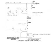
Is this V1?
It has "public" schematic (the later versions are not).
In this schematic the "current settings" resistor is R3//R7.
The required Rx value: 0.6/filament current is Ampere.
So for 0.22A: Rx=0.6/0.22 about 2.73R.
This means that 3.3 ...5R paralleled with appropriate potentiometer/resistor is good solution.
Attachments
- Home
- Amplifiers
- Tubes / Valves
- New DHT heater