Zung, why would you obtain measured parasitic components and then use a simulation to determine an RC snubber across a secondary HT winding without also doing an in-situ measurement as per the quasimodo style ring test ?
Why not?
")
I actually have the Quasimodo, but I tried to broaden the scope and use it as an EMI filter as well, after realizing the commercial filters all ring.
Showing a scope screen without any description on what is being shown and what the test setup involved is imho just a waste of space.
Not anymore than the kind folks who are repeatedly posting "all amps/topologies/parts sound the same".
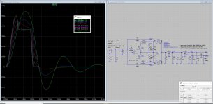
The pic comes from a previous post where I compared a fast diode and a Schottky, both tested with a Quasimodo. To waste a bit more screen estate, here's the 150nS FR608 fast diode under the exact same conditions.
Mark has generously shared Quasimodo with us (takes the guesswork out of snubbing, Zung) as well as a survey of transformer ringing to find the best (actually least-worst) diode available for a very affordable 3Euro (here: All articles | Linear Audio - thanks, Jan)...
I'm aware of both items; I'm just trying to include EMI filtering with the same topology. There's no more guesswork than the Quasi for the initial value of the cap, plus the modern comfort of the ".step" command that lets you compare different values.
Could someone explain to me the reasoning behind making the snubbing critically damped? If overdamped to any degree, the only downside is that the resistor gets warmer. What am I missing?
You're missing the engineering showoff. Overdamping is totally cool.
Last edited:
Zung, you seem to be using a different test jig for diode testing than the default Quasimodo setup used for snubber testing - is your setup described anywhere? I presume the test jig is hammering the diode under conditions that won't be experienced in normal amp power supplies? Did you only have an 800V pn diode to compare to a 20V schottky?
Chris, the snubber capacitance lowers the resonant circuit frequency (with the winding leakage inductance), and diverts transient current through it (rather than mainly being consumed by the winding), and I'm likely missing some other subtleties. There may be no noticeable disadvantage to having the snubber grossly over-damped. Aiming for a critically damped response is just an easier visual target to aim for. 'Critical' does not imply 'exact' imho, as the test jig conditions are not exactly the same as the in-situ conditions.
It's also worth appreciating that the quasimodo scope plots are meant to look 'severe' so as to observe any transient response - in normal amp operation it can be quite difficult to discern any transient, depending on the circuit/conditions, and I've found it very difficult for valve amp type B+ supplies to identify any rectifier transient even when resorting to a soundcard/spectrum analyser to look at the noise floor.
Critical damping gives the fastest dissipation of energy. If you overdamp then you're basically increasing the resistance, so you're not burning off as much energy, making the snubber less effective. (Imagine if you used infinite resistance, you would have no snubber at all!)Could someone explain to me the reasoning behind making the snubbing critically damped? If overdamped to any degree, the only downside is that the resistor gets warmer. What am I missing?
synchronous rectification has it all, but it's still too low voltage.
Not so low. The Auirs 1170s is good for 200v with the right mosfet in half wave and can easily do 600v in a bridge. Tibi has a thread about it.
The advertised benefit of a synchronous bridge for alleviating commutation noise may be reasonable, but I haven't seen any threads here that go to performance assessment of that aspect (there is nothing in the long thread by Tibi/tvicol - Ideal bridge rectifier GB except a link to a simulation). The turn-off characteristic could well depend on how the FET control is set up, so not all apples may be the same.
@trobbins, nattawa did a great job by measuring and comparing in this thread https://www.diyaudio.com/forums/pow...320-ideal-bridges-cool-quiet.html#post6138250
Regards,
Tibi
Regards,
Tibi
Last edited by a moderator:
Tibi, I wouldn't say nattawa did 'a great job', and in review the comparison was quite flawed wrt 'noise'.
The scope plots are ambiguous as to what is shown and labelled - it appears that a probe tip was placed 'near' the large 10mF output capacitor, with no indication of where the ground clip was placed, or a photo shown of layout.
And it wasn't an apples-apples comparison, as it seems that the kool-brg has an smt 2.2uF bypass cap across the +/- terminals, which is likely to be the dominant suppressor of the ringing shown from the Sanken diode bridge.
What could have been a better comparison test is to custom place a smt 2u2 cap across the Sanken bridge legs, or remove the 2u2 cap from the kool-brg module. An analog scope may also be limited in identifying an apples-apples comparison, and it may be better to use a probe connected to a known point and use soundcard/spectrum analyser software to see a subtle difference that is down in the noise floor.
PS. there is also a concern with comparing a 50A pn diode bridge to a synch solution when the application is really down at the <<10A device rating region.
Last edited:
LT4320 maximum allowed voltage is mainly limited by his internal regulator. This internal regulator is self-powered by mosfet-bridge. In the same time drain sense voltage are internally connected for each mosfet to internal controller. This make impossible to use an external regulator to increase LT4320 voltage operation.
Regards,
Tibi
Regards,
Tibi
- Home
- Amplifiers
- Tubes / Valves
- How to use solid state rectification the best way