Eli,
Which Ferrite Beads suppress 120Hz, 240Hz, 360Hz . . .
But do not lower the 60Hz voltage?
How steep is that frequency response curve of the ferrite bead.
I hope there are no HF or VHF RF frequencies generated by the B+ secondary, solid state diodes, and capacitor input filter.
I usually think of ferrite beads in the filament leads, when they are in a Grounded Grid HF or VHF linear amplifier.
Last edited:
I hope there are no HF or VHF RF frequencies generated by the B+ secondary, solid state diodes, and capacitor input filter.
When large valued cap. I/P filters are employed, the conduction angle is small and the ripple current pulses are large. That large ripple current waveform is highly "triangular" in shape. Applying Fourier's Theorem to that shape informs us that overtones of the ripple fundamental extending well up into the RF range are present. Dig into the archives, both here and over on AA, for my posts about "hash" filtration.
Eli is right, which is almost always true, too. I've been building power supplies 'from scratch' for nearly 60 years now and counting. I can say this-about-that...
The advent of the high voltage Schottky is nothing short of magic in suppressing reverse switching transient noise in rectification. Are they worth the money compared to a modestly cheaper snubber arrangement? Mmmm... maybe, just due to simplicity.
That's the first. The second is, to take the above advice regarding 'smaller C1' in the filtering chain. I used to think bigger-is-better, but after having acquired a nice oscilloscope that also does Fourier transforms (frequency domain), I found that my bigger-is-better go-to was false. Smaller is better, except when 'so small that it doesn't hold enough energy' becomes the problem.
22 to 47 microfarads is just fine for C1. Followed by a rather small (even 'puny') choke to L/f block the higher harmonics. Then a nice 100 to 220 uF cap as the main reservoir. And another 'puny' choke. And another even bigger capacitor as the impedance-dropping final C3 in the chain.
Works like a charm, and preserves the highest voltage you can achieve. Chokes are awesome in that preservation goal.
Some like to add resistors. I prefer puny chokes. 1/4 henry, to 1 henry. Let the capacitors do the heavy lifting, but the chokes for squashing the HF noise.
And FULL wave bridge rectification.
Or, for the voltage-challenged (as you've been hinting), even use FULL wave voltage doubling. Its hardly any trouble, and done with delicate regard to the 'wavy' (unwanted) possibilities on the delivered power, can be quite nice. I've cobbled together quite a few 350 V power supplies with a 1 to 1 isolation transformer from the surplus bin, 120 V feed, using the doubling technique. And once the scope shows the output power (under load) to be nice and clean, well ... there you are.
GoatGuy
A big 1st filter cap. can work well, IF appropriate actions are taken. The capacitance of the many wire turns in a "typical" filter choke provide a path for HF noise to "sneak" past said choke. A LC section made from a high current RF choke and a 1000 pF. mica or C0G ceramic cap., between the 1st filter cap. and the "typical" filter choke, removes the HF noise routine CLC filtration doesn't cope with well.
The Rise Time of the B+ power supply is controlled by the leakage reactance of the power transformer, DCR of the power transformer, the wiring to the rectifiers, and from there to the cap input filter.
0.35/Rise Time = Bandwidth for a Gaussian response.
I have heard of factors ranging from 3 to 4.5, instead of 3.5 for certain natural and digital responses that determine bandwidth.
But those are all in the same range of bandwidth.
The definition of frequency ranges of RF, VHF, UHF have changed over the decades.
But there is a limit to the top frequency that is generated at any significant large amplitude.
A resistor at room temperature has a noise level of approximately -174dBm/Hz.
But even that has a frequency limit, or else an extremely small shorted resistor would be smoking from the power of near infinite bandwidth.
I have to report that the highest frequency electrical signal I have ever measured is 500GHz (yes, 0.5 Terrahertz).
For higher frequencies than that, there is an extreme gap; the only other high frequencies I have ever measured are from Infrared to Ultra Violet.
Just My Opinion.
Last edited:
Eli is right
And FULL wave bridge rectification.
Or, for the voltage-challenged (as you've been hinting), even use FULL wave voltage doubling. Its hardly any trouble, and done with delicate regard to the 'wavy' (unwanted) possibilities on the delivered power, can be quite nice. I've cobbled together quite a few 350 V power supplies with a 1 to 1 isolation transformer from the surplus bin, 120 V feed, using the doubling technique. And once the scope shows the output power (under load) to be nice and clean, well ... there you are.
GoatGuy
Agree,
Big fan of voltage multiplier after trying it for myself-
Used free'd up 5v winding (SS rect) from PT to supply -19V needed for grid bias thru voltage tripler... clean DC that was listen verified.
Jim
Last edited:
Michal, have you done a simple design and simulation of your B+ supply using PSUD2? That will push you to measure the winding resistances of the power transformer, and to choose a load current level on the B+, and can then provide an estimate of the B+ voltage you will get depending on your rectifier configuration. Perhaps start with that first, and settle on the voltage and current requirement of your amplifier.
Then you can look at the diode current level and confirm if the simplest UF4007 type diode will be sufficient for your need. I'd advise against using a diode with a higher current rating than is necessary, as that can be a pathway for more noise to get through to the B+ filter.
You can also look at further LC filtering to determine what likely final B+ ripple voltage you should expect, and what current a choke needs to work at. You also need to be practical about how much ripple voltage applied to the output stage will then couple to the speaker and could then be heard as hum. Making the B+ filtering more complex, and expecting ripple voltages down in the uV level is just fanciful thinking that that will then give you some tangible reduction in speaker hum level.
If you have a choke and are concerned about its impedance with frequency then you can set up an impedance measurement using your soundcard and software like REW - that will show the frequency where the choke impedance peaks and then starts to fall, and depending on your soundcard you may be able assure yourself that the impedance is sufficiently high out to 100kHz (and so should be adequate for its job to suitably attenuate any LF hum and noise when used with a suitable C for LC filtering).
I'd also recommend providing photos of your power supply layout and wiring scheme, as even with ok parts, the final level of noise/hum can be influenced by how you construct the power supply.
Last edited:
Do you listen to the diodes, or your own diy amps with ss diodes, to come to that conclusion? Or have you listened to any commercial amps?
here we go again......they like the sound of their ss rectifiers.....
but here is what i do, i use high ampere diodes in my tube amps, why? because number 1 they are so cheap nowadays, number 2 higher rated rectifiers have lower losses and so runs cooler...and i am not referring to those high fallutin' rectumfiers either....
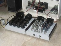
i built this 16kt88 triode wired pushpull amp using a 16A bridge rectifier....
Attachments
Last edited:
Are you suggesting a ss diode dissipating 0.1W in a valve amp chassis is going to operate at a junction temperature that tangibly improves diode life when the diode is say 5A rated versus 1A rated ? Any comment about using a larger diode die size and how that may have other consequences such as increased junction capacitance or stored charge, or lower junction voltage at the time of turn-off?
The query in post #7 was related to the OP's comment "Every time I found solid state diodes to sound harsher and worse in highs than vacuum tube ones." and begs the view that the OP may not have adequately designed or implemented his power supplies.
The query in post #7 was related to the OP's comment "Every time I found solid state diodes to sound harsher and worse in highs than vacuum tube ones." and begs the view that the OP may not have adequately designed or implemented his power supplies.
Are you suggesting a ss diode dissipating 0.1W in a valve amp chassis is going to operate at a junction temperature that tangibly improves diode life when the diode is say 5A rated versus 1A rated ? Any comment about using a larger diode die size and how that may have other consequences such as increased junction capacitance or stored charge, or lower junction voltage at the time of turn-off?
The query in post #7 was related to the OP's comment "Every time I found solid state diodes to sound harsher and worse in highs than vacuum tube ones." and begs the view that the OP may not have adequately designed or implemented his power supplies.
it is my personal preference, not strictly based on engineering, but higher current diodes will have more thermal mass, and my posting is not in anyway recommending that others follow....
i am just following what PRR has said in past posts, "build it like a tank" within reason of course...
....i am just following what PRR has said in past posts, "build it like a tank" within reason of course...
So it is my fault?
But I would not build it like a tank and then complain that it "sound harsher and worse in highs", clank clank clank.
So it is my fault?
But I would not build it like a tank and then complain that it "sound harsher and worse in highs", clank clank clank.
Еasy to have the best of both worlds, why even argue? 😀
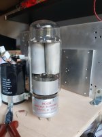
Attachments
I dare to claim that any statements on harshness etc. of plain SS rectification with 1N400x diodes vs. superfast Schottky's etc. and even tube rectifiers won't pass any DBT. It's just expectation biased.
The only advantage I see in tube vs. SS rectifiers is when some certain sag, hence signal compression, is wanted in guitar amps.
Best regards!
The only advantage I see in tube vs. SS rectifiers is when some certain sag, hence signal compression, is wanted in guitar amps.
Best regards!
A big 1st filter cap. can work well, IF appropriate actions are taken. The capacitance of the many wire turns in a "typical" filter choke provide a path for HF noise to "sneak" past said choke. A LC section made from a high current RF choke and a 1000 pF. mica or C0G ceramic cap., between the 1st filter cap. and the "typical" filter choke, removes the HF noise routine CLC filtration doesn't cope with well.
Hi Eli, would it have to be an rf choke or would a low value speaker crossover choke in the sub mH range work (in the negative rail of course). Silver mica OK for the cap?
Hi Eli, would it have to be an rf choke or would a low value speaker crossover choke in the sub mH range work (in the negative rail of course). Silver mica OK for the cap?
Silvered mica parts are fine.
A speaker crossover choke might work. This sort of part definitely works. Make certain to pick something with adequate current handling capability.
Thanks. Cannibalized chokes from an old tuner might work in a preamp PS. I forgot to ask about what time constant we are shooting for.
Here is good article about time constants.
a Direct Heating Triode blog: LCR Phono preamplifier Part 3
But he calculates time constant of LC network only with its DC resistance which I think is not accurate.
Small resistor before any cap will not affect the voltage so much (5 volts drop is still ok), or the RF blocking choke. Will be 500 microhenry enough?
Would be good to put these two in series before any capacitor?
Why the bypassing of electrolytes with several values can make more problems than it solves?
So it is my fault?
But I would not build it like a tank and then complain that it "sound harsher and worse in highs", clank clank clank.
who is to blame you? it happened that your post made a lot of sense to me....
i am a happy camper here, reading and enjoying your posts....
silicon rectifiers as now ubiquitous and so darned cheap....it is a shame not to take advantage...
Last edited:
I dare to claim that any statements on harshness etc. of plain SS rectification with 1N400x diodes vs. superfast Schottky's etc. and even tube rectifiers won't pass any DBT. It's just expectation biased.
The only advantage I see in tube vs. SS rectifiers is when some certain sag, hence signal compression, is wanted in guitar amps.
Best regards!
they have been led to believe.......i do not suffer from that kind of nonsense thankfully....plain jane silicon rectifier can be very satisfying, after all it is all of the circuit that mattered in the end, not just rectifiers...
Last edited:
- Home
- Amplifiers
- Tubes / Valves
- How to use solid state rectification the best way