As a side thread from the original one for the Push-Pull ( Shunt Cascode Driver meets UNSET for Push-Pull ), I post here a preliminary version of a pentode-driving-a-pentode single ended amp with a DF of 8.6 (Zout is 0.93 Ohm considering 0.2 Ohm of secondary winding) without any gnfb, and capable of 30Wrms with 1.34% THD.
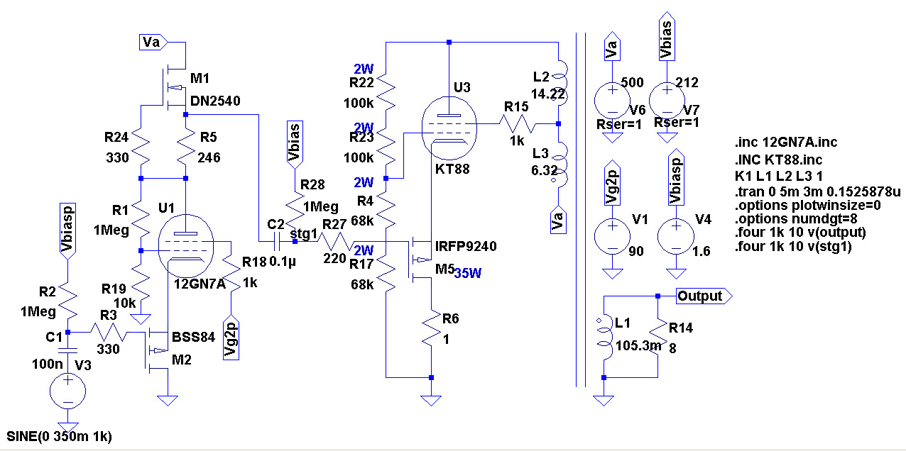
The driver is a pentode CCS loaded with a-g1 feedback, whilst the output is a pentode with a-g1 feedback plus the same amount of UL.
I've used this transformer as reference: TTG-KT88SE - Tube output UL transformer [3kOhm] KT88 / 300B SE - Shop Toroidy.pl
I can get 0.089% THD at 1 Wrms:
The driver is swinging 70Vpp at 0.015% THD:
I can get 0.32% THD at 10 Wrms:
The driver is swinging 220Vpp at 0.06% THD:
I can get 0.57% THD at 20 Wrms:
The driver is swinging 320Vpp at 0.12% THD:
I can get 1.34% THD at 30 Wrms:
The driver is swinging 400Vpp at 0.23% THD:
The driver is a pentode CCS loaded with a-g1 feedback, whilst the output is a pentode with a-g1 feedback plus the same amount of UL.
I've used this transformer as reference: TTG-KT88SE - Tube output UL transformer [3kOhm] KT88 / 300B SE - Shop Toroidy.pl
I can get 0.089% THD at 1 Wrms:
Code:
Harmonic	Frequency	 Fourier 	Normalized	 Phase  	Normalized
 Number 	  [Hz]   	Component	 Component	[degree]	Phase [deg]
    1   	1.000e+03	3.959e+00	1.000e+00	 -179.97°	    0.00°
    2   	2.000e+03	3.508e-03	8.861e-04	  -91.90°	   88.07°
    3   	3.000e+03	3.851e-04	9.727e-05	 -179.56°	    0.42°
    4   	4.000e+03	2.383e-05	6.019e-06	   13.08°	  193.05°
    5   	5.000e+03	1.936e-05	4.890e-06	   -0.11°	  179.86°
    6   	6.000e+03	1.483e-05	3.747e-06	   -0.20°	  179.77°
    7   	7.000e+03	1.271e-05	3.211e-06	   -0.19°	  179.78°
    8   	8.000e+03	1.113e-05	2.812e-06	   -0.17°	  179.81°
    9   	9.000e+03	9.894e-06	2.499e-06	   -0.15°	  179.83°
   10   	1.000e+04	8.905e-06	2.249e-06	   -0.13°	  179.84°
Total Harmonic Distortion: 0.089152%(0.089155%)
The driver is swinging 70Vpp at 0.015% THD:
Code:
Harmonic	Frequency	 Fourier 	Normalized	 Phase  	Normalized
 Number 	  [Hz]   	Component	 Component	[degree]	Phase [deg]
    1   	1.000e+03	3.477e+01	1.000e+00	    0.06°	    0.00°
    2   	2.000e+03	5.256e-03	1.512e-04	  -92.08°	  -92.14°
    3   	3.000e+03	6.492e-04	1.867e-05	    2.58°	    2.52°
    4   	4.000e+03	1.213e-04	3.487e-06	  171.70°	  171.64°
    5   	5.000e+03	9.866e-05	2.838e-06	 -179.89°	 -179.95°
    6   	6.000e+03	8.013e-05	2.305e-06	 -179.91°	 -179.97°
    7   	7.000e+03	6.867e-05	1.975e-06	 -179.98°	 -180.05°
    8   	8.000e+03	6.009e-05	1.728e-06	 -179.99°	 -180.05°
    9   	9.000e+03	5.342e-05	1.536e-06	 -179.99°	 -180.05°
   10   	1.000e+04	4.808e-05	1.383e-06	 -179.99°	 -180.05°
Total Harmonic Distortion: 0.015242%(0.015248%)
I can get 0.32% THD at 10 Wrms:
Code:
Harmonic	Frequency	 Fourier 	Normalized	 Phase  	Normalized
 Number 	  [Hz]   	Component	 Component	[degree]	Phase [deg]
    1   	1.000e+03	1.240e+01	1.000e+00	 -179.97°	    0.00°
    2   	2.000e+03	3.662e-02	2.953e-03	  -92.57°	   87.40°
    3   	3.000e+03	1.550e-02	1.250e-03	 -179.47°	    0.51°
    4   	4.000e+03	5.075e-04	4.092e-05	   65.70°	  245.67°
    5   	5.000e+03	7.392e-04	5.961e-05	    1.79°	  181.76°
    6   	6.000e+03	4.516e-05	3.642e-06	   30.00°	  209.97°
    7   	7.000e+03	6.843e-06	5.518e-07	  -29.56°	  150.41°
    8   	8.000e+03	4.013e-05	3.236e-06	   -5.76°	  174.22°
    9   	9.000e+03	3.700e-05	2.983e-06	   -0.23°	  179.75°
   10   	1.000e+04	3.099e-05	2.499e-06	    0.04°	  180.01°
Total Harmonic Distortion: 0.320767%(0.320768%)
The driver is swinging 220Vpp at 0.06% THD:
Code:
Harmonic	Frequency	 Fourier 	Normalized	 Phase  	Normalized
 Number 	  [Hz]   	Component	 Component	[degree]	Phase [deg]
    1   	1.000e+03	1.092e+02	1.000e+00	    0.06°	    0.00°
    2   	2.000e+03	5.965e-02	5.462e-04	  -90.23°	  -90.29°
    3   	3.000e+03	2.869e-02	2.627e-04	    2.11°	    2.05°
    4   	4.000e+03	2.370e-03	2.170e-05	   97.59°	   97.53°
    5   	5.000e+03	1.253e-03	1.147e-05	 -177.33°	 -177.39°
    6   	6.000e+03	2.699e-04	2.471e-06	 -150.75°	 -150.81°
    7   	7.000e+03	1.610e-04	1.475e-06	  178.82°	  178.75°
    8   	8.000e+03	1.725e-04	1.580e-06	  178.06°	  178.00°
    9   	9.000e+03	1.551e-04	1.420e-06	 -179.91°	 -179.97°
   10   	1.000e+04	1.384e-04	1.267e-06	 -179.90°	 -179.97°
Total Harmonic Distortion: 0.060661%(0.060662%)
I can get 0.57% THD at 20 Wrms:
Code:
Harmonic	Frequency	 Fourier 	Normalized	 Phase  	Normalized
 Number 	  [Hz]   	Component	 Component	[degree]	Phase [deg]
    1   	1.000e+03	1.793e+01	1.000e+00	 -179.98°	    0.00°
    2   	2.000e+03	7.889e-02	4.399e-03	  -93.30°	   86.68°
    3   	3.000e+03	6.615e-02	3.689e-03	 -179.21°	    0.76°
    4   	4.000e+03	1.129e-03	6.297e-05	    2.38°	  182.36°
    5   	5.000e+03	7.964e-03	4.440e-04	    2.39°	  182.36°
    6   	6.000e+03	8.856e-04	4.938e-05	  100.30°	  280.27°
    7   	7.000e+03	1.101e-03	6.139e-05	 -175.67°	    4.31°
    8   	8.000e+03	2.349e-04	1.310e-05	  -63.35°	  116.63°
    9   	9.000e+03	2.290e-04	1.277e-05	    3.30°	  183.28°
   10   	1.000e+04	5.244e-05	2.924e-06	   38.57°	  218.55°
Total Harmonic Distortion: 0.575872%(0.575872%)
The driver is swinging 320Vpp at 0.12% THD:
Code:
Harmonic	Frequency	 Fourier 	Normalized	 Phase  	Normalized
 Number 	  [Hz]   	Component	 Component	[degree]	Phase [deg]
    1   	1.000e+03	1.587e+02	1.000e+00	    0.06°	    0.00°
    2   	2.000e+03	1.582e-01	9.970e-04	  -90.08°	  -90.14°
    3   	3.000e+03	1.109e-01	6.988e-04	    2.11°	    2.05°
    4   	4.000e+03	1.605e-02	1.012e-04	   90.48°	   90.42°
    5   	5.000e+03	9.257e-03	5.834e-05	 -176.41°	 -176.47°
    6   	6.000e+03	1.999e-03	1.260e-05	 -101.79°	 -101.85°
    7   	7.000e+03	5.240e-04	3.302e-06	   10.34°	   10.28°
    8   	8.000e+03	2.831e-04	1.785e-06	  136.14°	  136.08°
    9   	9.000e+03	2.713e-04	1.710e-06	 -176.22°	 -176.28°
   10   	1.000e+04	1.879e-04	1.184e-06	 -174.49°	 -174.55°
Total Harmonic Distortion: 0.122318%(0.122318%)
I can get 1.34% THD at 30 Wrms:
Code:
Harmonic	Frequency	 Fourier 	Normalized	 Phase  	Normalized
 Number 	  [Hz]   	Component	 Component	[degree]	Phase [deg]
    1   	1.000e+03	2.211e+01	1.000e+00	 -179.98°	    0.00°
    2   	2.000e+03	5.387e-02	2.436e-03	 -100.01°	   79.97°
    3   	3.000e+03	2.631e-01	1.190e-02	 -179.54°	    0.44°
    4   	4.000e+03	5.724e-02	2.589e-03	  -87.39°	   92.59°
    5   	5.000e+03	8.979e-02	4.061e-03	   -0.36°	  179.62°
    6   	6.000e+03	4.086e-02	1.848e-03	   88.38°	  268.36°
    7   	7.000e+03	4.102e-02	1.855e-03	  176.90°	  356.88°
    8   	8.000e+03	2.481e-02	1.122e-03	  -95.10°	   84.88°
    9   	9.000e+03	2.127e-02	9.618e-04	   -6.34°	  173.63°
   10   	1.000e+04	1.379e-02	6.236e-04	   81.49°	  261.47°
Total Harmonic Distortion: 1.342064%(1.344007%)
The driver is swinging 400Vpp at 0.23% THD:
Code:
Harmonic	Frequency	 Fourier 	Normalized	 Phase  	Normalized
 Number 	  [Hz]   	Component	 Component	[degree]	Phase [deg]
    1   	1.000e+03	1.980e+02	1.000e+00	    0.06°	    0.00°
    2   	2.000e+03	3.429e-01	1.732e-03	  -90.26°	  -90.32°
    3   	3.000e+03	2.900e-01	1.465e-03	    2.37°	    2.31°
    4   	4.000e+03	6.541e-02	3.304e-04	   88.28°	   88.22°
    5   	5.000e+03	4.225e-02	2.134e-04	 -174.48°	 -174.54°
    6   	6.000e+03	1.313e-02	6.633e-05	  -97.64°	  -97.70°
    7   	7.000e+03	6.336e-03	3.200e-05	   15.17°	   15.12°
    8   	8.000e+03	2.241e-03	1.132e-05	   78.78°	   78.72°
    9   	9.000e+03	1.403e-03	7.084e-06	 -148.60°	 -148.65°
   10   	1.000e+04	6.102e-04	3.082e-06	 -145.97°	 -146.03°
Total Harmonic Distortion: 0.230306%(0.230306%)
Attachments
Since the cathode of the output tube is being driven in this amp, tying the screen to a fixed voltage (with respect to GND) will result in positive drive to the screen (with respect to cathode). I believe zintolo is attempting to make the voltage between screen and cathode stay more or less constant with the UL, and doing that has some advantages.
It is kind of similar to the Unity-Coupled amp in that respect, where the screen and cathode are moving around but following each other. This one is not quite as constant, though, since there is the tube's distortion added to the UL signal but not the cathode drive side.
It is kind of similar to the Unity-Coupled amp in that respect, where the screen and cathode are moving around but following each other. This one is not quite as constant, though, since there is the tube's distortion added to the UL signal but not the cathode drive side.
Last edited:
Yes. In a "normal" grid biased power tube with cathode grounded and UL applied, there is drive to g2. With this scheme, that drive is partially countered. Whether that's good or bad depends on whether you believe feedback by means of UL is beneficial or not.
Edit: Chris H, not sure I see where this is a differential anything. Can you explain?
Edit: Chris H, not sure I see where this is a differential anything. Can you explain?
Last edited:
My work thus far doesn't lead me to believe so much that UL (plate-to-screen feedback) isn't beneficial, but that it is inferior to plate to grid feedback. So if I have excess gain and I want to apply it as feedback, I'll apply it in the way that has the most positive benefit. I think that zintolo's sims at different ratios showed inferior performance if I remember correctly.
Chris, the main advantage that drives me to the series differential stage with the p-channel fet is the simplicity.
Chris, the main advantage that drives me to the series differential stage with the p-channel fet is the simplicity.
Current through the series'ed vacuum valve plus MOSFET is the product of the differential input voltage between valve G1 and MOSFET gate and effective Gm. The pair's Gm could be back-calculated as the reciprocal sum of reciprocals of each device's Gm. The two inputs have very high common mode rejection in the sense that the current source present in a parallel diff stage is effectively infinite (ain't even there).
My question is: what advantage is gained over conventional parallel diff stages? There's no power supply immunity and no even order distortion cancelling.
All good fortune,
Chris
My question is: what advantage is gained over conventional parallel diff stages? There's no power supply immunity and no even order distortion cancelling.
All good fortune,
Chris
Yes, best performance (from simulations) comes with same amount of feedback for g1 and g2, apparently.I think that zintolo's sims at different ratios showed inferior performance if I remember correctly.
About PSRR, the advantage I see in this design is that it is needed to have 70Vpp from the driver to get 1 Wrms and 400Vpp to get 30 Wrms, so the same amount of injected ripple will result in a higher S/N ratio in this configuration, so the injected noise will be less audible.
I'm sorry, I'm a newbie and I don't know the debate about UL do/don't. Can I ask you to point me to some readings? I can imagine is a matter of "the worst the output transformer is, the worst the UL feedback will be", so phase issues, transformer distortions reinjected into the output tube, etc...Whether that's good or bad depends on whether you believe feedback by means of UL is beneficial or not.
70 Vpp= 24 Vrms
400 Vpp = 140 Vrms
30 Wrms = 15,4 Vrms on 8 ohm
If the output stage in your strange configuration has a gain of 10 (probably less) and the ratio of the trafo is 20 ( just an example) = 3200 ohm
The OT you mentione has 19,36
With 24x10 = 240 / 20 = 12 Vrms = 18 watt
With 140 x 10 = 1400 /20 = 70 Vrms = 612,5 watt
Which kind of calculation have you done?
Then, if you don't know the real electric specification of the trafo in which way you can simulate it?
At low frequency which is the figure of L; and at high frequency how much are the parasitic?
The simulation are almost good for a short frequency range where the trafo can be considered (almost) ideal
Then the ratio s/n is measured in one certain way and not following as you wrote.
Then, as you call it a tube amp?
Last, is it possible to see some your real prototype?
Or you have only simulation
Ciao
Walter
I'm sorry waltube,
you are going on chasing me in all threads saying that I'm wrong in everything without even trying to understand the circuits nor reading the thread to get details. This is just personal bitterness.
Please stop acting this way.
I will ask moderators to take actions.
you are going on chasing me in all threads saying that I'm wrong in everything without even trying to understand the circuits nor reading the thread to get details. This is just personal bitterness.
Please stop acting this way.
I will ask moderators to take actions.
This looks pretty interesting... ") More understanding is required; I have personal issues just building an amp from schematic I have not yet gotten to understand completely.
More understanding is required; I have personal issues just building an amp from schematic I have not yet gotten to understand completely.
I like the cathode drive. It is a difficult load compared to g1, but it does not change so radically as when g1 goes positive.
On the CCS plate load, have you considered a cascode? all the times I tried just a single, when I went to cascode them I liked the result better. Say a DN3545N3 underneath? Perhaps under a 10M40 as its bias is about double a DN2540( thereby giving the lower FET more voltage to work with).
cheers,
Douglas
More understanding is required; I have personal issues just building an amp from schematic I have not yet gotten to understand completely. I like the cathode drive. It is a difficult load compared to g1, but it does not change so radically as when g1 goes positive.
On the CCS plate load, have you considered a cascode? all the times I tried just a single, when I went to cascode them I liked the result better. Say a DN3545N3 underneath? Perhaps under a 10M40 as its bias is about double a DN2540( thereby giving the lower FET more voltage to work with).
cheers,
Douglas
Lots of interesting ideas here. Hopefully you'll build some prototypes to test the concept.
That does make sense actually as I think about it. This is a pretty clever design IMO.
Last, is it possible to see some your real prototype?
Or you have only simulation Ciao Walter
Most of these simulations are variations of my UNSET, and CED push-pull amp designs. This sim is a copy of the UNSET with a CCS load on the driver pentode, which I have done in other amp designs to get more gain. My Unset uses a fairly high value resistor to a B+ in the 450 to 650 volt range, resulting in plenty of gain.
I designed the UNSET after several years of work with TV sweep tubes. The primary goals were good triode like performance with tubes that require a low voltage on G2 and the lack of a negative voltage supply for low cost single supply designs.
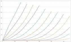
I did test the design with conventional audio tubes including the 6550, KT88, 6L6GC, 6V6GT and several others. I did not experiment with UL operation, since I get triode like curves from a CED, the Compound Electron Device made with a TV sweep (line output) tube, I feel that UL is not needed. The curves shown are a small 6GF5 paired with a FQPF5P20 mosfet.
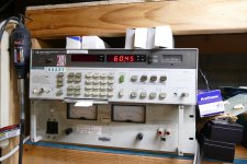
Prototypes have existed in both SE and P-P configuration for the last 3 years. All have performed well at power levels to 40 WPC in SE, and 250 WPC in P-P.
UNSET is coming?
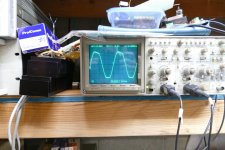
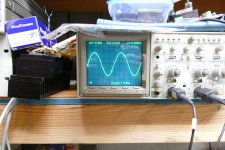
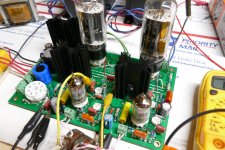
The SE prototype is well on it's way to becoming the next Tubelab board.
Board #1 is squeezing a clean 30 watts through that Toroidy, and a very dirty 60 watts when I cranked the drive up to see if it would blow up. Yes, it ate my guitar playing at neighbor annoying levels, and I'm in a concrete basement.
Attachments
-
 CED_1-00.jpg261.2 KB · Views: 496
 -
 P3990453-x.jpg615 KB · Views: 193
 -
 P3990454-x.jpg682.8 KB · Views: 208
 -
 P3990456-x.jpg558.7 KB · Views: 182
 -
 P3990455-x.jpg668.2 KB · Views: 408
 -
 P3990459-x.jpg878.4 KB · Views: 412
 -
 P3990434-x.jpg786.8 KB · Views: 473
 -
 P3990423_x.jpg951 KB · Views: 482
 -
UnSET_V22_schematic.pdf130 KB · Views: 210
Thank you Douglas, I simulated it simple to see how it will perform, but the simple/cascode will be something to test when it will become real.On the CCS plate load, have you considered a cascode?
At the moment I'm more focused on the PP just because I already have all needed trafos on hand.
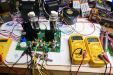
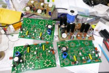
Yes, The schematic I posted is from the Eagle PCB design. If it goes in the board, it must be in the schematic. That's why you see doubled mosfets, lots of mounting and ventilation holes, and some funny stuff around the output tubes. That is a matrix of jumpers so that any octal tube can be used just by changing the jumpers. Non octal tubes can be mounted off board.
The board seen with the Toroidy OPT has its output stages wired in parallel from a single driver stage to do PSE into a 1500 ohm OPT and get 60 watts at clipping.
I am working on a parts list now but there are lots of different tubes to try, including some 4D32's off board.
The board seen with the Toroidy OPT has its output stages wired in parallel from a single driver stage to do PSE into a 1500 ohm OPT and get 60 watts at clipping.
I am working on a parts list now but there are lots of different tubes to try, including some 4D32's off board.
- Home
- Amplifiers
- Tubes / Valves
- Single Ended: the pentode retaliation