FB Effect on Power Supply Ripple
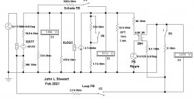
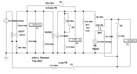
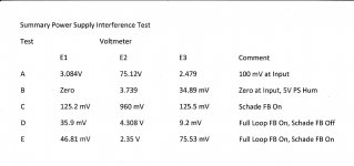
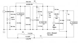
The new numbers for the OPT winding resistances are included in these simulations. The first simulation is simply a 100 mV input so stage gains can be calculated.
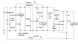
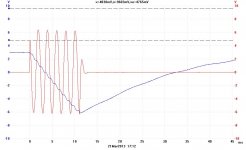
The 2nd sim sets the input at zero but adds a PS ripple of 5V. A PS hum voltage appears on the load resister. The 3rd sim applies Schade NFB, the hum on the load resister increases.
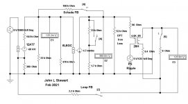
The 4th sim shews Schade FB unhooked & normal FB applied. Notice a bucking voltage almost as large as the PS ripple appears at E2 in opposition to the PS ripple.
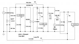
In the last sim both Schade FB & normal FB are applied, the hum on the load resister persists. The bucking voltage at E2 is smaller.
All this is normal, more sims later.")
And somebody pls check my numbers in the summary table.
The new numbers for the OPT winding resistances are included in these simulations. The first simulation is simply a 100 mV input so stage gains can be calculated.
The 2nd sim sets the input at zero but adds a PS ripple of 5V. A PS hum voltage appears on the load resister. The 3rd sim applies Schade NFB, the hum on the load resister increases.
The 4th sim shews Schade FB unhooked & normal FB applied. Notice a bucking voltage almost as large as the PS ripple appears at E2 in opposition to the PS ripple.
In the last sim both Schade FB & normal FB are applied, the hum on the load resister persists. The bucking voltage at E2 is smaller.
All this is normal, more sims later.
And somebody pls check my numbers in the summary table.
Attachments
The Schade feedback arrangement requires more attention to detail in the design as well to ensure that the first stage can still operate properly. SE amps are sensitive to PS noise in general.
Without Shade feedback, you'll have a ton of distortion and poor damping. If you use global feedback, the stability of the amp will depend substantially on the quality of the output transformers used but you won't be as dependent on a quiet power supply.
Without Shade feedback, you'll have a ton of distortion and poor damping. If you use global feedback, the stability of the amp will depend substantially on the quality of the output transformers used but you won't be as dependent on a quiet power supply.
Each section of a power amplifier has its problems, tradeoffs, etc.
I keep 'hearing' threads mentioning power supply noise (No pun intended).
Learn how to build a very clean power supply. Low noise, low ripple, etc.
Learn how to control power supply ground loops.
Learn how to control power supply magnetic spray.
Fix the power supply before proceeding to use it in a single ended amplifier (and the same goes for using it in a push pull amplifier, only more so because of the widely varying current demands versus widely varying signal output level).
I hate to be so political, but Real Art and Real Science works.
Last edited:
I have nothing against Schade Negative Feedback.
Like so many methods and topologies, when properly implemented, it works very very well.
The Tacoma Narrows Bridge fell down because of badly implemented engineering knowledge of the time.
3 engineers said it would work, one engineer said it would fall. Who had the knowledge at that time?
Like so many methods and topologies, when properly implemented, it works very very well.
The Tacoma Narrows Bridge fell down because of badly implemented engineering knowledge of the time.
3 engineers said it would work, one engineer said it would fall. Who had the knowledge at that time?
Summary of Simulation Results
Here are the bare bones results of the sims without the schematics. Except for the PS example. All should be self explanatory.
Schade FB Only 13.75 db DF 3.34
Full Loop FB Only 12.02 DB DF 4.41
Both FB On 17.6 db DF 6.17
Full Loop Alone Adjusted for 17.6 DB NFB DF 10.1
PS Ripple Suppression, Full Loop FB Only 17.6 DB
Fans of Schade FB may not like these results. They are free to challenge them. But they better come with more than opinions.
Measurement results do matter & give a good prediction of how the circuit will perform.
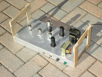
Some might wonder if I've built SE, here are some I can recall off the top. The last three were published by AudioXpress. With lots of actual measurement data, a lot more than just 'It Sounds OK'.
And photos, parts lists & construction advice.
SE Amps Built 6C4/41, 6SJ7/6V6, 6J5/50L6, 6J5/50L6 on 220V, 6AU6/6AQ5, 6EA7, 6LU8
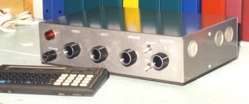
The 6AU6/6AQ5 amp is a fully integrated amp, complete with Baxandall Tone Controls & a PreAmp for Magnetic Phono. It runs every day in the workshop here, since 1968.
Here are the bare bones results of the sims without the schematics. Except for the PS example. All should be self explanatory.
Schade FB Only 13.75 db DF 3.34
Full Loop FB Only 12.02 DB DF 4.41
Both FB On 17.6 db DF 6.17
Full Loop Alone Adjusted for 17.6 DB NFB DF 10.1
PS Ripple Suppression, Full Loop FB Only 17.6 DB
Fans of Schade FB may not like these results. They are free to challenge them. But they better come with more than opinions.
Measurement results do matter & give a good prediction of how the circuit will perform.
Some might wonder if I've built SE, here are some I can recall off the top. The last three were published by AudioXpress. With lots of actual measurement data, a lot more than just 'It Sounds OK'.
And photos, parts lists & construction advice.
SE Amps Built 6C4/41, 6SJ7/6V6, 6J5/50L6, 6J5/50L6 on 220V, 6AU6/6AQ5, 6EA7, 6LU8
The 6AU6/6AQ5 amp is a fully integrated amp, complete with Baxandall Tone Controls & a PreAmp for Magnetic Phono. It runs every day in the workshop here, since 1968.
Attachments
Fans of Schade FB may not like these results. They are free to challenge them. But they better come with more than opinions.
I did an SE amp experiment on the bench with a 6384 at near 100% plate-to-grid voltage feedback and didn't feel performance was good enough, so I decided to get a high-gain input stage and take series voltage feedback from output tube plate to input stage cathode. I used some semiconductors to help boost the gain of the pentode input stage to ~2300 and was able to apply substantial feedback in a pretty short loop. The experiment yielded .046% distortion at 1W with a DF over 13, even with the output transformer outside the loop. Output transformer winding resistances dominate the Zout. Clipping occurred at 10W.
I've recently scaled it up to a small 60W transmitting triode and am getting 19W with less distortion and I'm getting ready to try some 100W triodes next.
Of course, a good clean power supply is mandatory with this approach (mine is a semiconductor regulator) but I feel it is an approach that can produce pretty good results.
I'm concerned that the output transformers that I have would not behave well enough over a wide enough frequency range for feedback around them to give good results, but I never really gave it a good try.
If the DF you got was for an 8R load that implies the OPT contributed (8/13) R to the output cct. Soumds about correct for the 6384 output Zout being close to zero. But going to SS means begging the often asked question, Why Not Go All SS? But NTL, an interesting experiment.
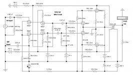
Attached a rather exotic cct with three kinds on NFB, one of them Schade. This needs a very good OPT, maybe a Plitron. Not exactly a circuit for amateurs to attempt.
Attached a rather exotic cct with three kinds on NFB, one of them Schade. This needs a very good OPT, maybe a Plitron. Not exactly a circuit for amateurs to attempt.
Attachments
If the DF you got was for an 8R load that implies the OPT contributed (8/13) R to the output cct. Soumds about correct for the 6384 output Zout being close to zero. But going to SS means begging the often asked question, Why Not Go All SS?
Zout was measured at about 0.6 Ohm. The secondary winding resistance plus the primary resistance reflected to the secondary accounts for almost all of that. If I recall correctly, feedback was a lot, like 35dB.
The reason for not going all SS is because I wanted to make a tube SE amp, but I'm okay with supporting the tubes with SS circuits. It's just a self-imposed requirement. That and I fell in love with the looks of the 100TH output tube, so looks is the other reason. I'm gonna have to build a cage over it, though, to keep things safe.
Another Trick Feedback Circuit to Puzzel Over
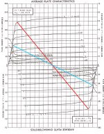
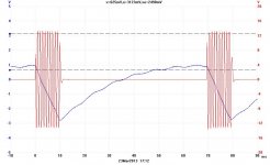
Whenever I'd built something in the last 25 or so years there are certain objectives in mind. This one tried PP 6V6s in Class AB2 pushed to the limit, a minimasl PS so could see overhead ability & try FB from output anodes to the upper grids of a PP differential stage. Off the top it manages 19 watts on the limited PS, 26 watts on a regulated PS. The internal NFB is about 8 DB. The OPT loadline is corrected for Class AB2 operation.
As usual, 'It Sounds OK'. What else should we expect when a typical speaker system brings with it 2% or more distortion? DF above 10 doesn't help any less than a DF of 100 since an 8 Ohm speaker adds about 6.5R in series with the amplifier. Do the math.
The pulsed waveforms are produced by an analogue gating circuit I built as a separate project. The audio generator was probably an HP 200CD.
This cct has been on DIY before, probably already seen by many. My apologies.
Attachments
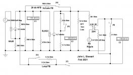

Your Edit is correct. Sometimes these schematics get so piled up they become difficult to read. This cct does better because the NFB factor is much larger, the FB current is driving back into a higher resistance.
To the driving cct the FB resistance looks like the FB resistance divided by the gain of the power tube.
To the driving cct the FB resistance looks like the FB resistance divided by the gain of the power tube.
- Status
- This old topic is closed. If you want to reopen this topic, contact a moderator using the "Report Post" button.
- Home
- Amplifiers
- Tubes / Valves
- Schade P2P and gNFB in RH807