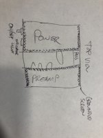
I have a plan for keeping the noise to a minimum. Long story short, imagine a footprint identical to that of the turn table divided into thirds the center third being a void, and the thirds on either side being wood boxes with either brass or copper plate (I literally just dug two large sheets of copper plate out of the side of the canyon wall weekend before last). The tubes stick into this void from either side. Rectifier tube from one side, preamp tubes from the other, transformers entirely contained inside the boxes. I've given thought to affixing some screen mesh around the inside of the boxes, and running that to ground as a faraday cage if it's not quiet enough. The only way for noise from the power supply to get to the preamp would be from the rectifier tube directly to the preamp tubes. No idea how effective it would really be, but that's what's been kicking around in my head for years. I live in a canyon that runs parallel to the face of the mountains/civilization, so external RF is likely really low (only a small handful of radio stations make it up here from Denver, and the canyon walls keep out most of the rest). My biggest problem is going to be that the power grid is not great, but there is literally a crew across the street right now replacing poles to rectify that exact situation.

I downloaded that app for designing power supplies. That's pretty slick! Unfortunately, I can not for the life of me figure out how to get the tube rectifier menu to populate. I don't have any Windows machines in the house (Mac/Linux), so I'm running the Mac version. Either that feature hasn't been ported yet, or the interface is not clear enough for me to be able to divine how to accomplish this...
If I can keep the power supply 100% tube for the giggles of it, that would be ideal. My fancy enclosure design kind of relies on it for symmetry, and I'm opposed to just about anything that's "for show". The obvious goal with this project is to end up with a serviceable phono preamplifier. The less obvious goal is to learn analog electronics, and this seems like a solid jumping off point. Hopefully it's a good thing that power supplies are simple relative to the amplifiers themselves, because that's the part I feel I have the poorest grasp on.
Attachments
If you're not using solid state diodes and a DC heater supply, then your dominate source of noise is very likely to be heater hum.
Are you thinking of sticking with AC heater wiring?
If you are, I think you know you'll have to keep the AC heater wiring hum fields out of the audio circuitry. Since the heaters are in the tubes themselves, and the tubes in a phono preamp will be working with input signal voltages of less than a millivolt, that will take careful attention to layout, wiring and lead dress.
Merlin Blencowe's Valve Wizard site has a good article about AC heater wiring: The Valve Wizard
There is a very good thread about heater wiring in general right here on diyAudio:
Heater Wiring - the Good the Bad and the Ugly
I hope that helps.
--
I assumed I'd be using DC heater wiring for that reason. The entirety of the power supply is still unknown at the moment. I'm really interested in going all tube, but I'm always open to convincing.
I'd recommend going DC for the heaters, for sure.
The problem is how to do that without solid state rectifier diodes. How would you do that?
--
The problem is how to do that without solid state rectifier diodes. How would you do that?
--
A reasonably well regulated B+ rail that's vacuum rectified, contains 0% SS, and eschews OS devices is possible. A 6CA4/EZ81 will be the rectifier. Active device regulation is out, as the voltage reference would either be a Zener diode (SS) or a gas discharge tube (OS). Fortunately, choke input filters are quite well regulated and 100% passive. LCRC topology should be more than good enough, for this project.
Look up choke I/P filters. For the setup to regulate, a minimum, critical, current must be drawn. That is accomplished by placing a bleeder resistor in parallel with the 1st filter capacitor. A good approximation of the critical current, in mA., is given by V/L. That works out to 1 Kohm of resistance per henry of inductance. Notice, larger inductances require smaller critical currents. Get Heyboer to wind a low current 50 H. part suited to choke I/P service. Less is definitely more, when it comes to the I2R heating produced by the bleeder resistor.
Rectifier forward drop is a loss that MUST be taken into account. Ignoring that forward drop, choke I/P filters yield approx. 0.9X the AC RMS value, but all of the RMS current. Take losses in the bleeder into account. In a nutshell, choke I/P filters are well regulated, current rich, and voltage poor. My guess for this 6CA4 PSU is 0.85X the RMS voltage as the DC rail voltage.
For simplicity you could always go with an LR8 regulator and a pass transistor for the B+ voltage. For filaments don't bother with the ancient LM317 anymore it wastes 3 volts. The MIC2941 has similar specs and drops only 0.6 volts at 1.25 amps.
Since LR8 is good for 400V and 10mA, and each tube will be consuming 300V and 2mA (12AX7) or 6.5mA (12AT7), why not regulate the B+ to each of the three tubes independently, each with its own LR8?
Thanks for the tip about MIC2941. That's a new one on me, and it looks great (600mV dropout voltage at 1A is pretty amazing). There's a fixed 12V version in the standard TO220-3 package. I should pick up a few of those.
--
Thanks for the tip about MIC2941. That's a new one on me, and it looks great (600mV dropout voltage at 1A is pretty amazing). There's a fixed 12V version in the standard TO220-3 package. I should pick up a few of those.
--
A reasonably well regulated B+ rail that's vacuum rectified, contains 0% SS, and eschews OS devices is possible. A 6CA4/EZ81 will be the rectifier. Active device regulation is out, as the voltage reference would either be a Zener diode (SS) or a gas discharge tube (OS). Fortunately, choke input filters are quite well regulated and 100% passive. LCRC topology should be more than good enough, for this project.
Look up choke I/P filters. For the setup to regulate, a minimum, critical, current must be drawn. That is accomplished by placing a bleeder resistor in parallel with the 1st filter capacitor. A good approximation of the critical current, in mA., is given by V/L. That works out to 1 Kohm of resistance per henry of inductance. Notice, larger inductances require smaller critical currents. Get Heyboer to wind a low current 50 H. part suited to choke I/P service. Less is definitely more, when it comes to the I2R heating produced by the bleeder resistor.
Rectifier forward drop is a loss that MUST be taken into account. Ignoring that forward drop, choke I/P filters yield approx. 0.9X the AC RMS value, but all of the RMS current. Take losses in the bleeder into account. In a nutshell, choke I/P filters are well regulated, current rich, and voltage poor. My guess for this 6CA4 PSU is 0.85X the RMS voltage as the DC rail voltage.
"Get(ting) Heyboer to wind a low current 50 H. part suited to choke I/P service" sounds like a pricey custom component... It wasn't stated as part of the design parameters, but cost is a consideration.
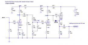
Beyond that, I don't 100% (maybe, no definitely, not even 50%) understand what's been said here, but it sure sounds good... This sounds like a schematic that someone like you would have to produce more or less from scratch rather than a massaging of something out of a 70 year old promotional booklet. Is this something you could produce (without any especially pricey components) to match the RCA-based schematic from rongon (reposted below to bring it into context)?
Attachments
I was talking about the B+ PSU, not the signal schematic.
Look here for a beginning discussion of choke I/P filtration.
The part will not be inexpensive, but it will also not be silly expensive. This custom part (thankfully) does not have to carry lots if current. 1 mA. for each 'X7 section, 3 mA. for each 'T7 section, and the bleeder loss are its workload. An inductor with a 20 mA. capability will get the job done. Thin copper magnet wire can be used in the many turns needed and the lamination stack will be modest in size. Those factors help contain costs.
Keep adding to the camel's burden and its back will break.
Look here for a beginning discussion of choke I/P filtration.
"Get(ting) Heyboer to wind a low current 50 H. part suited to choke I/P service" sounds like a pricey custom component... It wasn't stated as part of the design parameters, but cost is a consideration.
The part will not be inexpensive, but it will also not be silly expensive. This custom part (thankfully) does not have to carry lots if current. 1 mA. for each 'X7 section, 3 mA. for each 'T7 section, and the bleeder loss are its workload. An inductor with a 20 mA. capability will get the job done. Thin copper magnet wire can be used in the many turns needed and the lamination stack will be modest in size. Those factors help contain costs.
Keep adding to the camel's burden and its back will break.
I'd recommend going DC for the heaters, for sure.
The problem is how to do that without solid state rectifier diodes. How would you do that?
--
Historically, construction of a phono preamp that employs AC heating and achieves satisfactory residual hum levels is regarded as testing the mettle of a builder. While I refuse the challenge, meeting it has been done and it can be done again. AC heating sure looks like the answer to the no SS rectified and regulated requirements.
Spiral wound heaters, such as those found in 7025s and 6EU7s are a must. Biasing the heaters off B+ is necessary. Neurosurgical level attention to shielding, grounding, and layout are additional requirements. It most definitely aint easy!

This project seems to be headed towards a tube complement of 2X 12AX7LPSes, a 12AT7, and a 6CA4/EZ81. I'd like to see 3 separate filament windings: 1 for the 'X7s, 1 for the 'T7, and 1 for the rectifier. That's definitely safer when it comes to biasing off B+, as is needed. Requirements will be different for voltage amplifiers, buffers, and rectifier.
this was my first phono preamp i built...dead quiet if carefully built .I used a tl783 regulator for anode voltage though.On the other hand i didn't like the sound.Dark...really dark,not bad, but dark."Get(ting) Heyboer to wind a low current 50 H. part suited to choke I/P service" sounds like a pricey custom component... It wasn't stated as part of the design parameters, but cost is a consideration.
Beyond that, I don't 100% (maybe, no definitely, not even 50%) understand what's been said here, but it sure sounds good... This sounds like a schematic that someone like you would have to produce more or less from scratch rather than a massaging of something out of a 70 year old promotional booklet. Is this something you could produce (without any especially pricey components) to match the RCA-based schematic from rongon (reposted below to bring it into context)?
Hi
the best solution with Tubes and Riaa is the use of a regulated ss circuit.
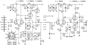
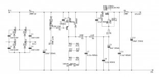
In attach the circuit I use for my Junior and other stuff plus a diagram( one channel)
It is dual mono with bridge with diodes separated; the residual ripple is almost zero and the results are on lab test.
Please do the circuit with are presented with test lab otherwise is always a problem to understand the results.
Walter
the best solution with Tubes and Riaa is the use of a regulated ss circuit.
In attach the circuit I use for my Junior and other stuff plus a diagram( one channel)
It is dual mono with bridge with diodes separated; the residual ripple is almost zero and the results are on lab test.
Please do the circuit with are presented with test lab otherwise is always a problem to understand the results.
Walter
Attachments

Armed with a few more microns of knowledge, I went back through to reread what's been said in the hope (certainty) that I missed some things.
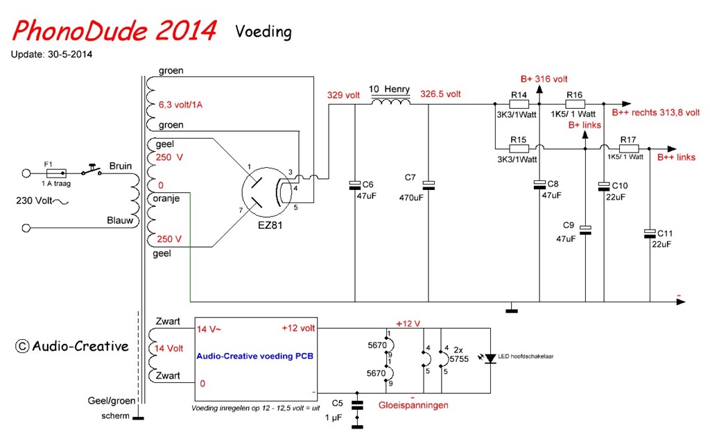
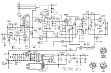
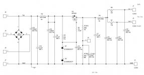
Koifarm posted this earlier in the thread (last post on page 2). It's the wrong mains voltage, etc., but it looks close to something that might work. It sounds like it'll take some effort to keep the hum down with this, but that seems like a good set of techniques to learn. Can this be massaged to work with US mains and the preamp we're working with?
It seems like a fair bit of that comes down to physical elements of assembly. One thing that comes to mind from my automotive hobby is shielding the heater wires a la Faraday. There exists stainless steel mesh wire looming for automotive racing applications. It wouldn't help with internal hum, but would shut down anything in the chassis. Combined with 7025s (TubeDepot lists some Electro Harmonix 7025s as new production, so there's a box checker), that might help quite a bit, and may even be serviceable.
That schematic employs a full wave center tapped (FWCT) rectifier into a Π section, AKA CLC, filter. It is poorly regulated. The FWCT 6CA4/EZ81 setup is a given. A choke I/P filter is how you fulfill your desires of 100% tubed and only current production, along with obtaining good regulation of the B+ rail voltage. TANSTAAFL! That schematic also employs a SS rectified and regulated DC heater supply.
Unless things have changed, the Sovtek 12AX7LPS costs less than the ElectroHarmonix (EH) 7025 and the true 7025 equivalent 'LPS has a fine reputation. BTW, both Sovtek and EH are brands owned by New Sensor.
Steer clear of Guitar Center, when buying signal tubes for phono preamp service. Purchase from a reliable dealer who is known to cull out "infant mortals", along with selecting low noise specimens. My go to guy is Jim McShane, but other suitable dealers are available.
Small signal tubes are going to be pulling a few milliamps constantly so supply regulation is of little concern. Regulation for minimizing noise? Sure. Current should be constant with this type of load.
That schematic employs a full wave center tapped (FWCT) rectifier into a Π section, AKA CLC, filter. It is poorly regulated. The FWCT 6CA4/EZ81 setup is a given. A choke I/P filter is how you fulfill your desires of 100% tubed and only current production, along with obtaining good regulation of the B+ rail voltage. TANSTAAFL! That schematic also employs a SS rectified and regulated DC heater supply.
Ah... That's probably what "Audio-Creative voeding PCB" is... I see now that's the heater supply section.
Unless things have changed, the Sovtek 12AX7LPS costs less than the ElectroHarmonix (EH) 7025 and the true 7025 equivalent 'LPS has a fine reputation. BTW, both Sovtek and EH are brands owned by New Sensor.
Has New Sensor positioned one brand over the other in terms of quality?
Steer clear of Guitar Center, when buying signal tubes for phono preamp service. Purchase from a reliable dealer who is known to cull out "infant mortals", along with selecting low noise specimens. My go to guy is Jim McShane, but other suitable dealers are available.
Sure. No argument here. It's a thought device. GCs are in every moderately sized urban-ish area and represent the most mass-produced, readily available, lowest common denominator. If it can be found in the glass case in a GC, it's readily accessible, and likely will be for the foreseeable future.
- Home
- Amplifiers
- Tubes / Valves
- Schematic hunt: RIAA Phono Preamp