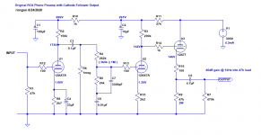
If you want no silicon in the circuit at all, you can replace the ZVN0545 MOSFET in Eli's design with a 12AT7 cathode follower. That will work well enough and give you a pretty nice phono stage. I whipped up a sketch that looks like it should work well.
Attachments
Well... This is fun... My nearly 8 month old daughter decided it would be great fun to climb on me and press buttons on the magic device in my lap. Somehow she immediately managed a key combination that I didn't know existed to post the above, all while blowing spitty raspberries. Meanwhile, my post count isn't high enough to get past every post needing moderator approval, so I genuinely don't know where I was in that thought, and it's almost assuredly not all that comprehensible in the state it was at the time she managed her key mashing feat...
So... I guess ignore what's up there and I'll try again.
That looks like a 120v power supply short of exactly what I'm after! We already knew 12AX7s are readily available, and I confirmed that 12AT7s are slightly less available, but still seem to be in production. 7025s, as an otherwise identical hum bucking improvement over the 12AX7s, seem to be available, but I'm not convinced they're in production.
Some questions about the schematic:
- Where is the trace on the bottom left intended to go? (chassis ground?)
- This is one channel, and 12AX7/12AT7s have two halves. Just to be sure I'm 100% following, the intent is to use 1/2 of each tube per channel, correct? I've seen many applications in the guitar amp (mono) universe that have multiple halves in use, but for some reason (I've always assumed spatial/manufacturing constraints) only the one half of a given tube. I know this is an ubernoob question, and I'm fairly certain I know the answer, but want to be 100% certain rather than assume.
- In roughly the center of the schematic, you have a 262k resistor with "(360k || 1M)" below it inn blue. I assume that means the 262k can be swapped with either of the others? What would be gained in doing so?
Last edited:
Great home parenting story! The spitting raspberries part was cute. Gotta love it.
It's rumored that the Sovtek 12AX7LPS has a really quiet heater which makes it sort of a contemporary 7025. I've used 12AX7 tubes of all kinds and I don't think there's enough difference between them to get all hung up on it. I personally like the old Telefunken 'smooth plate' ECC83s best, but they're collectors' items now. Russian 6N2P is also a good substitute for 12AX7, but it has a 6.3V heater (pins 4 and 5) with pin 9 as an internal shield (connect that to ground). That's actually a good thing. 6N2P would be a great tube to use. But really, any good 12AX7 (ECC83, 7025, etc.) ought to work fine.
The trace on the bottom left is 'ground'. Best practice would be to connect that to the chassis at the input and use insulated input jacks with their grounds connected to the chassis at the input.
You can wire it up so that each 12AX7 and 12AT7 has one side used for the Left channel and the other side used for the Right channel. Or you could use one 12AX7 for the Left channel and the other 12AX7 for the Right channel, but you'd still need to split the two 12AT7 halves between the Left and Right channels. I'm not sure there's any advantage to doing it one way or the other.
In either case, the heater supply will need to floated above ground to about +75V DC. That's because the 12AT7 cathodes will be about +150V above ground, which exceeds the maximum heater-cathode voltage spec.
Also, I'd add a simple 1N4148 diode or a neon lamp between the cathode and grid of the 12AT7, to protect the tube from cathode stripping at turn on (in the few seconds before the tube begins conducting). That's just a preventative tweak; nothing to do with the sound.
262k resistors may not be easy to find, so you can use a 360k and a 1M resistor wired in parallel to make roughly 264k ohms if you have to.
Attachments
Last edited:
In either case, the heater supply will need to floated above ground to about +75V DC. That's because the 12AT7 cathodes will be about +150V above ground, which exceeds the maximum heater-cathode voltage spec.
This requires some explanation to get enough juice from my feeble mind grapes.
Also, I'd add a simple 1N4148 diode or a neon lamp between the cathode and grid of the 12AT7, to protect the tube from cathode stripping at turn on (in the few seconds before the tube begins conducting). That's just a preventative tweak; nothing to do with the sound.
Ah. Yup. Makes sense. See that all the time doing double duty as a power indicator lamp.
262k resistors may not be easy to find, so you can use a 360k and a 1M resistor wired in parallel to make roughly 264k ohms if you have to.
Right. Gotcha. I interpreted the || as the logical OR operator (software engineer). The math for paralleled resistors doesn't immediately pop out to my brain like some.
How would I go about a power supply for this? These always seem to be separate, and I don't understand why?
'Floating' the heater supply is pretty simple once you see it in a schematic. You might want to read through Merlin Blencowe's Valve Wizard website. Merlin's a great resource.
How to design valve guitar amplifiers
Here's Merlin's explanation of heater supplies for valves (tubes):
The Valve Wizard
Check out the section titled "Heater Elevation".
Actually in this case that wouldn't work. The 1N4148 diode doesn't make any light, and the neon lamp (if used properly for this purpose) will only light while it's protecting the tube, and will go dark once the circuit operates.
The only requirements are for a +300V DC 'plate' supply (B+) capable of delivering a minimum of about 15mA current draw. There are many ways to put this together.
The simplest, but least effective, would be to get a suitable power transformer (Antek makes good toroid power transformers for reasonable cost) with a 270V secondary, which would yield about +350V DC for the raw B+ supply. Then use multiple stages of filtering (decoupling) to knock that down to the +300V DC you need. With that much voltage drop available, you could make a nice quiet B+.
A step up from that would be to make a regulated DC supply. But that would require transistors and all that. The most commonly used one is the so-called Maida design.
This is Pete Millett's version:
High Voltage Regulator
There are fancier ones that may perform better. But this is a perfectly good starting point.
The heaters will require either 6.3V or 12V. It doesn't really matter which, unless you use 6N2P tubes, in which case it will have to be 6.3V. For a phono preamp, you'll want to rectify the heater supply so it's DC instead of AC. That will reduce the hum considerably. And since you'll already be rectifying the heater voltage, you might as well regulate it too. If you make a 12V DC regulated heater supply, it will only need to supply 0.45 amperes, which is within the capabilities of an LM317T regulator IC. That will need a heatsink, though.
Again, Pete Millett has a good, basic version to look at:
Regulated DC filament supply
John Broskie, of TubeCAD fame, also sells a kit you can use for a fancier 12V DC heater supply.
Tr-PS-1 low-voltage, regulated 12Vdc power supply
Finally, the reason you often see the power supply put in a separate chassis from the audio circuits, connected by an umbilical cable, is to get the transformers and rectifier diodes away from the sensitive, high gain audio circuits. The transformers and rectifiers create a hum field that can get into the audio circuits. With a lower gain phono stage for moving magnet cartridges, you should be able to get away with a single chassis holding both the audio circuitry and the power supply circuitry. However, great care needs to be taken to keep the electrical and magnetic fields from the transformers and noise from the rectifiers out of the audio circuitry.
The math for figuring out the value of paralleled resistors is pretty easy.
R1*R2/R1+R2 = Resistance of R1 in parallel with R2
--
How to design valve guitar amplifiers
Here's Merlin's explanation of heater supplies for valves (tubes):
The Valve Wizard
Check out the section titled "Heater Elevation".
Ah. Yup. Makes sense. See that all the time doing double duty as a power indicator lamp.
Actually in this case that wouldn't work. The 1N4148 diode doesn't make any light, and the neon lamp (if used properly for this purpose) will only light while it's protecting the tube, and will go dark once the circuit operates.
How would I go about a power supply for this? These always seem to be separate, and I don't understand why?
The only requirements are for a +300V DC 'plate' supply (B+) capable of delivering a minimum of about 15mA current draw. There are many ways to put this together.
The simplest, but least effective, would be to get a suitable power transformer (Antek makes good toroid power transformers for reasonable cost) with a 270V secondary, which would yield about +350V DC for the raw B+ supply. Then use multiple stages of filtering (decoupling) to knock that down to the +300V DC you need. With that much voltage drop available, you could make a nice quiet B+.
A step up from that would be to make a regulated DC supply. But that would require transistors and all that. The most commonly used one is the so-called Maida design.
This is Pete Millett's version:
High Voltage Regulator
There are fancier ones that may perform better. But this is a perfectly good starting point.
The heaters will require either 6.3V or 12V. It doesn't really matter which, unless you use 6N2P tubes, in which case it will have to be 6.3V. For a phono preamp, you'll want to rectify the heater supply so it's DC instead of AC. That will reduce the hum considerably. And since you'll already be rectifying the heater voltage, you might as well regulate it too. If you make a 12V DC regulated heater supply, it will only need to supply 0.45 amperes, which is within the capabilities of an LM317T regulator IC. That will need a heatsink, though.
Again, Pete Millett has a good, basic version to look at:
Regulated DC filament supply
John Broskie, of TubeCAD fame, also sells a kit you can use for a fancier 12V DC heater supply.
Tr-PS-1 low-voltage, regulated 12Vdc power supply
Finally, the reason you often see the power supply put in a separate chassis from the audio circuits, connected by an umbilical cable, is to get the transformers and rectifier diodes away from the sensitive, high gain audio circuits. The transformers and rectifiers create a hum field that can get into the audio circuits. With a lower gain phono stage for moving magnet cartridges, you should be able to get away with a single chassis holding both the audio circuitry and the power supply circuitry. However, great care needs to be taken to keep the electrical and magnetic fields from the transformers and noise from the rectifiers out of the audio circuitry.
The math for figuring out the value of paralleled resistors is pretty easy.
R1*R2/R1+R2 = Resistance of R1 in parallel with R2
--
Last edited:
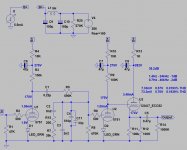
The Audio Innovations 200MM phono also recommended:
https://www.diyaudio.com/forums/tub...tions-s200-schematic-request.html#post6290217
I use it with 5751 tubes and LED bias.
https://www.diyaudio.com/forums/tub...tions-s200-schematic-request.html#post6290217
I use it with 5751 tubes and LED bias.
Attachments
'Floating' the heater supply is pretty simple once you see it in a schematic. You might want to read through Merlin Blencowe's Valve Wizard website. Merlin's a great resource.
How to design valve guitar amplifiers
Here's Merlin's explanation of heater supplies for valves (tubes):
The Valve Wizard
Check out the section titled "Heater Elevation".
Gotcha. So that lives in the power supply, and I just realized the heaters are not on the schematic you posted above.
Actually in this case that wouldn't work. The 1N4148 diode doesn't make any light, and the neon lamp (if used properly for this purpose) will only light while it's protecting the tube, and will go dark once the circuit operates.
Ah. Just kidding then.
Finally, the reason you often see the power supply put in a separate chassis from the audio circuits, connected by an umbilical cable, is to get the transformers and rectifier diodes away from the sensitive, high gain audio circuits. The transformers and rectifiers create a hum field that can get into the audio circuits. With a lower gain phono stage for moving magnet cartridges, you should be able to get away with a single chassis holding both the audio circuitry and the power supply circuitry. However, great care needs to be taken to keep the electrical and magnetic fields from the transformers and noise from the rectifiers out of the audio circuitry.
I know why they're physically separated, I meant the schematics. I get only diagraming one channel since the other is identical, but I don't understand why the power supply is never in the same context as the amplifier section.
The math for figuring out the value of paralleled resistors is pretty easy.
R1*R2/R1+R2 = Resistance of R1 in parallel with R2
Yeah. I meant it's not math I can do in my head. My best friend is a pretty hard core UHF EE, and he either does the math in his head, or has just done it enough that he knows about what values are about as close as can be had. I was thrown off by the || symbol (and naivete), which means "OR" in many software languages.
I know why they're physically separated, I meant the schematics. I get only diagraming one channel since the other is identical, but I don't understand why the power supply is never in the same context as the amplifier section.
Oh, sorry. Actually, it's best practice to include the power supply schematic with the audio circuit schematic, since really they're one and the same. But for convenience, you'll commonly see the audio circuit shown by itself with only the voltages indicated. I was being lazy.
It's common practice in schematics for tube circuits to not show the heater circuits, especially when using indirectly heated tubes. Heater supplies for indirectly heated tubes are pretty generic. A 12V DC supply for two 12AX7s and a 12AT7 will need to deliver 450mA of current, which means you can use any number of 12.6VAC transformers capable of delivering 1A or more. You can use an LM317T on a small heatsink to regulate down to 12V DC. (It doesn't have to be exactly 12.6V DC. 12V DC will be close enough, and reducing the heater voltage by 5% might have some benefits.) You could even use a 12V DC SMPS/wall wart for the heater supply.
If you intend to use a 6.3V DC heater supply, you'll want to find a 9V AC transformer for the raw supply if you want to regulate down to 6.3V DC. The LM317 has a dropout voltage of 3V DC, so you need to start with at least 9VDC to regulate down to 6.3V DC.
LM317 Dropout Voltage - Electrical Engineering Stack Exchange
Last edited:
Assuming I'm dead set on sticking with all tube circuitry, including the power supply, are there any proven tube rectified power supply schematics running around similar to the RCA catalog variety that would play nice with the RCA derived preamp above? Taking input into account, I think a 5AR4 may be the better choice. Seems to be even more available than the 5U4 in the guitar store context (though I personally have more 5U4s on hand, which probably colored that assumption more than it should have). It seems power supplies are overall simpler than amplifiers, but so much of my attention throughout the years has been focused on the amplifiers, especially since tube rectification is a relatively rare bird. Despite the relative simplicity, it seems I have a steeper learning curve ahead of me on that front.
PS, I looked at your profile, and it's too bad you're across the river from Rip's old tree rather than across the canyon from Fender's old tree. We could have some very good beers... I also used to be semi-pro guitarist (I brought a jazz flavor to an otherwise rock outfit), my wife ran sound for numerous high profile Jazz outfits, I used to be a guitar tech for a lot of jazz and rock guitarists, and one of my other hobbies is luthiery. The enclosure for this will undoubtedly be made from random little leftover bits of exotic hardwoods from one of my giant piles of exotic hardwoods.
PS, I looked at your profile, and it's too bad you're across the river from Rip's old tree rather than across the canyon from Fender's old tree. We could have some very good beers... I also used to be semi-pro guitarist (I brought a jazz flavor to an otherwise rock outfit), my wife ran sound for numerous high profile Jazz outfits, I used to be a guitar tech for a lot of jazz and rock guitarists, and one of my other hobbies is luthiery. The enclosure for this will undoubtedly be made from random little leftover bits of exotic hardwoods from one of my giant piles of exotic hardwoods.
Last edited:
Octal rectifiers are pretty overkill for an RIAA preamp. There are plenty of small 6.3V heated rectifiers that would do the job fine. If you used something like a 6CA4, you wouldn't even need a separate 5V winding.
Like I said above, the initial premise was that I want to use readily available, current production tubes for future proofing. As a proxy indicator of what is readily available, I used Guitar Center since they're everywhere, and one could just walk in and get whatever is needed at a moment's notice. My worldview is heavily colored by the guitar amplifier background, and I recognize that blindspot. Stepping back one notch and looking at the tubedepot site, I see that Electro Harmonix and JJ are currently making the 6CA4 tubes. It's a minor compromise (but not really), and definitely good enough; meets the criteria in principle. Especially during a pandemic, I'm going to be ordering everything online anyway...
Is there a pre-existing, proven power supply schematic out there in the RCA catalog style that would play nicely with the RCA-based preamp a page or two back?
Is there a pre-existing, proven power supply schematic out there in the RCA catalog style that would play nicely with the RCA-based preamp a page or two back?
Using valve rectifiers in phono preamps is useless.Phono preamps aren't ment to colour the sound that way.Guitar amplifiers are a different wold.
If you really want something professional go with the Luxman cl 34 or cl 40 schematic.The only other better design is EMT JPA 66 who's schematic is not available, but it's an increase in price from 3000 dollars to 60 000...
The rest of designs aren't necessarily bad but it's better to try a very high commercial standard first and Luxman is just a killer design centerd on 12ax7.
This isn't just another phono preamp:
Luxman CL-34 on thevintageknob.org
Luxman CL-40 on thevintageknob.org
CL-40 LUXMAN - HiFi-Do McIntosh/JBL/audio-technica/Jeff Rowland/Accuphase
Last edited:
I do not disagree with any of your objections. I'm willing to allow some slippage in the ultimate sound quality in favor of following a particular design ethos. I write code for modern electronics stuff all day, every day. This is meant to be the polar opposite. I also like carburetors despite the fact that I live in the mountains and see as much as 3K' altitude change any time I go anywhere (at least 1K' every single trip). A little compromise isn't always a bad thing.
EDIT: I came back due to an email indicating a response (and running a time consuming simulation for work). I see that you've edited your reply above since I wrote and posted this reply (the initial post was just the first line). I've not yet read the edited reply, but will do so now. Just wanted to be clear since the response below seems to hint at something I missed in the edit.
EDIT: I came back due to an email indicating a response (and running a time consuming simulation for work). I see that you've edited your reply above since I wrote and posted this reply (the initial post was just the first line). I've not yet read the edited reply, but will do so now. Just wanted to be clear since the response below seems to hint at something I missed in the edit.
Last edited:
Well...i don't necessarily try to dissapoint you, but it's better to start something the right way then modify, it to your needs if you still think it's helpful.Phono world is already a very diverse one and borrowing a clear cut vision from one of the best manufacturers is a good start.
Last edited:
I already built some mesa engineering,marshall, fender vox and peavey clones in the past so i should know what i'm talking about when reffering to the guitar head world as a separate one.Besides, powerful guitarheads are running class AB which means that the valve rectifiers "sound" can easily be heard, but phono preamps work mostly class A Adding powerful rectifiers like the ones used in guitar heads will simply make no difference once the supply voltage is set and properly filtered. You'll be switching between valves and normal silicon rectifiers and won't hear any difference.
Last edited:
I can understand wanting to go all-tube, super-purist on this. Please understand that this kind of retro power supply will perform much worse than a more modern power supply using solid state rectification and voltage regulation. A retro passive supply will be more expensive. It will be larger. It will be noisier. But it will be simpler.
Many vintage 1950s and early 1960s RIAA preamps used rectifier tubes and R-C filtering for the power supplies. The Dyna PAS3 springs to mind. That uses a 12X4 rectifier tube, which is similar to the 6CA4 mentioned earlier, and solid state rectifier diodes to make a DC heater supply (DC +12V/-12V). But I guess that has some silicon too. Some silicon is pretty much inescapable in a phono preamp.
You could download PSUD2 - a passive power supply modeling app - and design your own PSU.
Download
Designing a passive B+ supply is pretty straightforward. You need to know what the raw rectified voltage will be from the power transformer you choose, by knowing how much current your audio circuitry will draw from the supply and the regulation of your transformer. Figure out how many volts you need to drop from the raw supply to the audio circuits, and from there use Ohm's Law to calculate resistor values. Large value 400V rated capacitors and good high wattage resistors are easy to find these days, so that won't be a problem.
The resulting passive B+ supply could be good enough if you're not super picky. But a phono preamp has a lot of gain and is working from very low source voltage (around 1mV or so). Guitar amps work on similar signal levels, but a bit of hum is considered acceptable there. Not so with phono preamps. Any audible hum at all will drive you nuts.
A truly expert builder can design a wiring and chassis layout that yields quiet enough results from a passive filter PSU and AC heaters, but you'd have to be really good to get it quiet enough for a phono preamp.
A lot of people here have been down this road before you. People are giving you good, sound advice. I'd listen to them.
--
Last edited:
Powersupply for a riaa amp is not sensitive for anything. In fact anything that rectifies,
a simple C-R-C-R-C is all that is needed as the current consumption is constant ( we are
totally in class A and very little swing). All that matters is low hum which depending
on layout and grounding. Filtening mains and outside RF is importent.
Using extended stabs are a waste of time & money.
a simple C-R-C-R-C is all that is needed as the current consumption is constant ( we are
totally in class A and very little swing). All that matters is low hum which depending
on layout and grounding. Filtening mains and outside RF is importent.
Using extended stabs are a waste of time & money.
Well, actually...
I built a phono preamp for my brother, something like 25 years ago.
I used the old Handmade Electronics RCA RIAA PCB, but took the output right off the second 12AX7 and direct coupled that to a 12AT7 cathode follower. So the audio circuit ended up being very similar to what's being discussed here.
I built a passive power supply using a small transformer with 500VCT 40mA and 6.3VAC 2A secondary windings.
The plate supply used UF4007 rectifier diodes, C-R-C-R-C filtering.
I didn't regulate the heaters, but I did DC rectify them, filtered by a C-R-C filter of 10,000uF-2.2R-10,000uF. I got 6V DC in the end, which is close enough.
I put the whole thing inside a steel 2U 19" rackmount chassis. The AC cord, power switch, mains fuse, power transformer and rectifiers are all the way at one end of the chassis, with the input/output jacks, audio PCB and tube sockets at the other end. The power transformer is inside a small aluminum project box, inside the main chassis. I guess that aluminum box insulates the audio circuits from any RF hash from the rectifiers, but not electromagnetic fields from the transformer (I didn't understand that back then). But that's what I did.
Much to my surprise, the preamp turned out really well. Noise is very low. t's very 'musical.' My brother feeds the preamp with a Grado MI cartridge, and it works fine for that. A couple years ago I had it in my place to give it a checkout. I replaced the power supply caps and fired it up, driven by a Denon DL110 cartridge. I thought it sounded really good. I liked it, a lot.
However, it was a real pain to get the heater voltage correct with a C-R-C filter. If I were to build that now, I'd definitely use an LM317 based regulator for the 6V DC supply, especially since it only needs to deliver 450mA. Otherwise, I think the C-R-C-R-C passive B+ supply is probably good enough.
So yeah, I'm a hypocrite. But I mean well.
--
Last edited:
- Home
- Amplifiers
- Tubes / Valves
- Schematic hunt: RIAA Phono Preamp