Which benefits fo you find at different percentages? From what I've seen main points are:I have experimented with 20%, 40%, 50%, and 80% taps. Of course, for a given tube type, Real Ultra Linear only occurs at a specific Tap %. But some of the benefits can be partially realized, even if the tap is at a different % than what is optimum.
Higher % means generally:
- lower internal impedance;
- higher tolerance on the loadline (softer knee);
- better linearity;
- lower power.
I've tried it time ago.It would be nice to try the cathode tap as an alternative to UL
The trafo I have now is a 3.5 kRaa to 0-4-8-16 Ohm with only 28 H primary inductance. I grounded the 4 Ohm tap and connected my 8 Ohm speaker to the 0 and 4 Ohm taps. The "problem" is that standard CFB taps have same dc resistance, but 0-4 Ohm part has bigger wire than 4-16 Ohm, so different resistance for the same number of turns, and this brings to differences on the push and pull side. Soundwise is not bad at all, but it will need for sure more swing to correctly drive the output tubes with the standard 10% CFB. I was just using 3,4%.
And, a higher tap % gives less gain.
Given a fixed bias voltage, and standing current, that is one reason for lower power at higher Tap %.
There are papers that discuss push pull Ultra Linear, that describe the 3rd order harmonic harmonic and most specifically 3rd order Intermodulation distortion.
There is an optimum Tap % for a particular tube type.
Another idea I had was to use Rod Coleman's Shunt Cascode ( Shunt Cascode Power Valve Driver ) plus a mosfet concertina to drive a power amp with 10% cathode feedback: in case of the KT77 at 450V I'd need 70Vpp + {[(450-70)V x2] x10%} = 70 Vpp + 76Vpp = 146 Vpp. I've obtained 250Vpp with 1% THD (mainly 2nd) from half a cheap 12AX7.That is why so many Unity gain cathode feedback circuits will use positive feedback (there is a resistor from the output tube plate to its driver tube plate).
You can ground the 4 Ohm tap, and connect the 8 Ohm speaker across from the Common tap to the 8 Ohm tap.
The problem is not connecting the speaker to the correct tap. It can float, it is still DC connected to ground, and it is safe.
The problem is, you can not connect the 8 Ohm resistive load, with the scope across it.
The properly grounded (and properly safe) scope will short out part of the output transformer secondary windings, if you do it that way.
So. . .
Instead connect a 4 Ohm load across the 4 Ohm tap, and the Common tap.
Connect the scope probe probe tip to the Common tap, and the scope probe ground tip to the 4 Ohm tap.
Then make your power, distortion, and frequency response measurements.
And, then connect a 4 Ohm load across the 16 Ohm tap, and the 4 Ohm tap.
Connect the scope probe probe tip to the 16 Ohm tap, and the scope probe ground tip to the 4 Ohm tap.
Then make your power, distortion, and frequency response measurements.
. . . Now, you have measured the performance of all of the secondary windings.
Do not worry about the slight difference in cathode voltages that connect to the Common and 16 Ohm taps.
That is only one of the most inner layers of the Onion. First, worry about the outer layers of the Onion.
Last edited:
Thanks again, I will give it a try again!Do not worry about the slight difference in cathode voltages that connect to the Common and 16 Ohm taps.
That is only one of the most inner layers of the Onion. First, worry about the outer layers of the Onion.
The reason why I'm connecting my 8 Ohm speakers to the 4 Ohm tap is because I don't like the 3.5 kOhm Raa and this way I can use the OPT as it would be a 7k Raa, and it sounds better this way (even if bandwidth is reduced).
A proper OPT would for sure improve the amp as it is now.
I've got some suggestion for the nJFET on this other thread:
Best jfet for hybrid cascode
and I reached 91 Wrms with 0,38% THD (3rd and 7th mainly):
Best jfet for hybrid cascode
and I reached 91 Wrms with 0,38% THD (3rd and 7th mainly):
Code:
Harmonic	Frequency	 Fourier 	Normalized	 Phase  	Normalized
 Number 	  [Hz]   	Component	 Component	[degree]	Phase [deg]
    1   	1.000e+03	3.823e+01	1.000e+00	    0.03°	    0.00°
    2   	2.000e+03	4.356e-03	1.139e-04	   86.84°	   86.81°
    3   	3.000e+03	1.373e-01	3.592e-03	   -2.68°	   -2.71°
    4   	4.000e+03	1.093e-03	2.859e-05	   12.75°	   12.72°
    5   	5.000e+03	4.655e-03	1.218e-04	  148.06°	  148.02°
    6   	6.000e+03	4.368e-04	1.142e-05	  -89.08°	  -89.11°
    7   	7.000e+03	4.304e-02	1.126e-03	   -0.90°	   -0.93°
    8   	8.000e+03	1.353e-04	3.539e-06	  129.20°	  129.17°
    9   	9.000e+03	1.190e-03	3.114e-05	   89.71°	   89.68°
Total Harmonic Distortion: 0.376791%(0.378500%)
Attachments
I've done some further tests on the amp with EL34, and then optimized the applied concepts on LTSpice.
The results at 52 Wrms with a pair of EL34 are as follows:
The results at 52 Wrms with a pair of EL34 are as follows:
Code:
Harmonic	Frequency	 Fourier 	Normalized	 Phase  	Normalized
 Number 	  [Hz]   	Component	 Component	[degree]	Phase [deg]
    1   	1.000e+03	2.867e+01	1.000e+00	   -0.03°	    0.00°
    2   	2.000e+03	2.410e-02	8.406e-04	  -87.61°	  -87.58°
    3   	3.000e+03	1.558e-01	5.436e-03	    0.02°	    0.05°
    4   	4.000e+03	1.467e-02	5.117e-04	  -89.27°	  -89.24°
    5   	5.000e+03	1.191e-02	4.155e-04	 -176.29°	 -176.26°
    6   	6.000e+03	1.084e-03	3.782e-05	   95.36°	   95.39°
    7   	7.000e+03	2.360e-02	8.230e-04	    2.17°	    2.20°
    8   	8.000e+03	6.300e-04	2.197e-05	   86.74°	   86.77°
    9   	9.000e+03	1.310e-02	4.569e-04	 -179.41°	 -179.38°
Total Harmonic Distortion: 0.561911%(0.562431%)
Attachments

I've noticed that, at full volume, without gnfb there are some sibilant S in certain recordings . Adding gnfb eliminates the problem at full volume but makes the sound less pleasant at low&mid volumes. In the guitar amps I build for me, I always add a variable gnfb from the secondary of the output transformer to the PI (plus two other filters for lows and highs).
Has anyone ever succesfully added a variable gnfb control on an Hi-Fi?
Has anyone ever succesfully added a variable gnfb control on an Hi-Fi?
I think to go further with gnfb you will need a more accurate transformer model, including primary resistance, capacitance and leakage inductance. There's no dominate pole currently which will make closing the gnfb loop tricky.
Thanks baudouin0,
last weekend I've implemented a pot and a switch for the gnfb.
Going lower than 10 kOhm caused udible low frequency oscillation, so my idea is to implement a 15 kOhm resistor in series with a 50 kOhm lin pot with push-pull switch to disable the gnfb, in order to give no to low gnfb at low volumes and add more at high volumes and adapt the sound to what we are listening: Adele is better with no gnfb, James Taylor live at Beacon Theater is better with high gnfb, Rage Against The Machines depend on the track and the volume I'm listening them to, Mozart's Requiem is better with no gnfb at all.
Current OPTs are quite bad in all parameters and they will be substitued when all details will be determined (and most probably it will become a quad/sextet of EL34s each channel).
You may be able to improve the LF stability by taking R7 10k and adding a 33K in series. Then bypass the 33k with a 4u7-10uF film. This will produce some lead lag compensation.
I had a play with your schematic. I would suggest you take the plate to plate feedback from the 40% UL taps as your quite close to instability.

Now the amp is split in two monoblocks with a footprint of 430x250 mm (standard Hammond cases), and they are too big and not so nice.
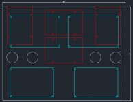
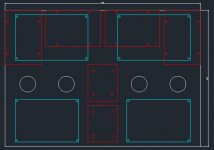
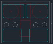
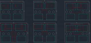
I would like to rebuild the amp as a single stereo chassis and yesterday evening I've sketched some possibilities. One implies new transformers (preferrable from a performance point of view), the others uses existing ones (economically preferrable).
I would like to ask your suggestions on them.
Just consider that:
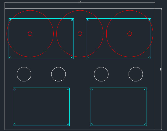
- Chassis and EL34 holes are white;
- Transformers are red;
- Pcbs are blue (power supply on top and PI + Driver on bottom)
First one is with a new set of transformers: right impedance, right UL taps (23% instead of 40%), higher primary inductance, etc.. vs higher costs. It's 370 x 300 mm. I would keep this option as last by now due to costs.
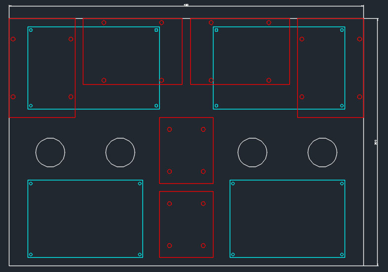
Second one is with the EI transformers I have now, including the inductors. The space kept on top of the inductors will be used to install fuse holders.
It's 430 x 300 mm.
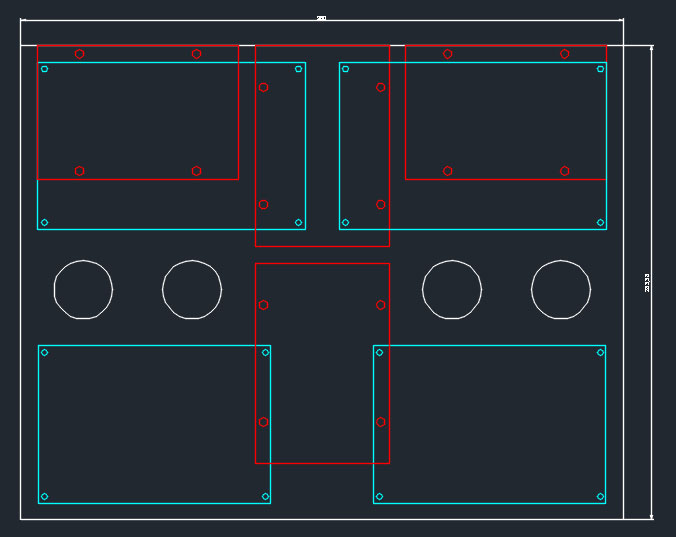
Third one is again with EI transformers, without inductors, with a T configuration. What I don't like of this configuration is that power transfomer is too close to volume pot on the central-front part, so it will be most probably prone to catch noise. It's 360 x 280 mm.
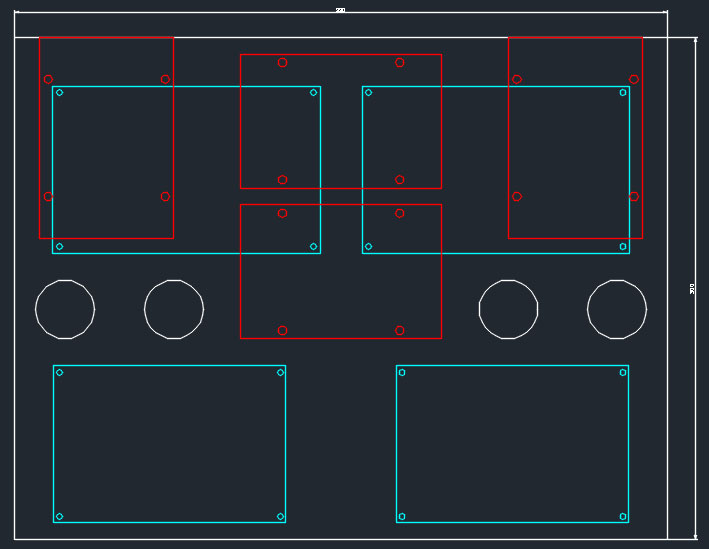
Fourth one is again with EI transformers, without inductors, rotating each transformer by 90°. It's 390 x 300 mm.
Thanks
Roberto
I would like to rebuild the amp as a single stereo chassis and yesterday evening I've sketched some possibilities. One implies new transformers (preferrable from a performance point of view), the others uses existing ones (economically preferrable).
I would like to ask your suggestions on them.
Just consider that:
- Chassis and EL34 holes are white;
- Transformers are red;
- Pcbs are blue (power supply on top and PI + Driver on bottom)
First one is with a new set of transformers: right impedance, right UL taps (23% instead of 40%), higher primary inductance, etc.. vs higher costs. It's 370 x 300 mm. I would keep this option as last by now due to costs.
Second one is with the EI transformers I have now, including the inductors. The space kept on top of the inductors will be used to install fuse holders.
It's 430 x 300 mm.
Third one is again with EI transformers, without inductors, with a T configuration. What I don't like of this configuration is that power transfomer is too close to volume pot on the central-front part, so it will be most probably prone to catch noise. It's 360 x 280 mm.
Fourth one is again with EI transformers, without inductors, rotating each transformer by 90°. It's 390 x 300 mm.
Thanks
Roberto
Attachments

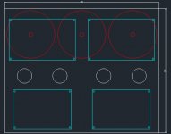
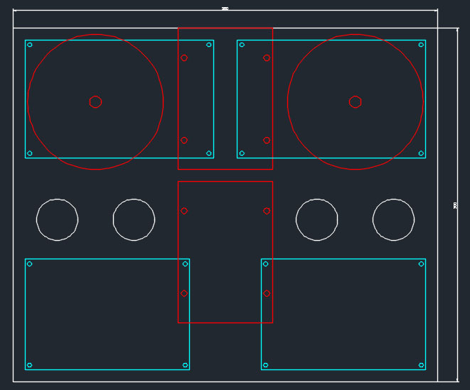
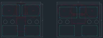
This is another version that could be a good compromise between costs and performance, implementing just the output transformers with the right specs and keeping the EI transformers as they are, without inductors (or mounted internally on one side of the chassis). It's 360 x 300 mm.
...don't turn the image upside down or it could seem offensive 🙄
...don't turn the image upside down or it could seem offensive 🙄
Attachments
- Home
- Amplifiers
- Tubes / Valves
- improvements on 12AX7 12AT7 EL34 schematic?