I just noticed how the circuit I'm using now:
improvements on 12AX7 12AT7 EL34 schematic?
Is similar on the feedback paths to the idea that Mona posted here:
Sim of RCA Tube Manual 50 Watt Amplifier - results and questions
improvements on 12AX7 12AT7 EL34 schematic?
Is similar on the feedback paths to the idea that Mona posted here:
Sim of RCA Tube Manual 50 Watt Amplifier - results and questions
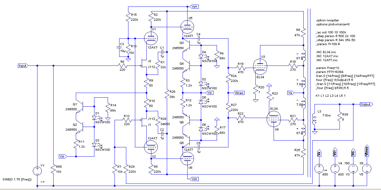
I know some like to keep the channels separate - but is better to put them together at the input. This avoids the cross ground hum loop where current goes up one screen on the input and back down the other. This tends to occur if you place the PT over the top of the cables. Hectors layout of keeping the transformers at the sides or back helps here. Yes your JFET-12AX7 has similarities with high gain pentode. However the phase spitter is in front of this and the pentode provides gain, more common mode rejection and buffering to remove the unequal impedance. There's also no buffer after the pentode - so maybe not so much in common.
Last edited:
Another layout suggestion - easier to keep signal, output and power supply seperate.
M&A TVA-10
Thank you Hector, I will check your suggestion this evening, and see how to apply it to my amp.
The division I've done by now is:
- PSU pcbs on the back side;
- Output tubes in the middle (so closer to the PSUs, but this keeps preamp more far from PSU, that should be more sensitive to noise than the output tubes);
- Preamps on the front side.
Thanks, well noted.I know some like to keep the channels separate - but is better to put them together at the input. This avoids the cross ground hum loop where current goes up one screen on the input and back down the other. This tends to occur if you place the PT over the top of the cables. Hectors layout of keeping the transformers at the sides or back helps here.
I interpreted "my" circuit as a Mona/RCA amp with the pentodes of the 6CM8s acting as an high gain phase splitter, so without the triodes' stages. The EL34's plate to grid feedback is still there (even if reconfigured à la Yves Montmagnon / Gingertube), and the EL34's plate to driver's cathodes (sources in my case) feedback is still there too, plus gnfb.Yes your JFET-12AX7 has similarities with high gain pentode. However the phase spitter is in front of this and the pentode provides gain, more common mode rejection and buffering to remove the unequal impedance. There's also no buffer after the pentode - so maybe not so much in common.
Leant that from experience. Try and arrange so your L and R input stage is close together. Usually means putting the input valves near the middle of your box and output valves on each side for example.
Whilst I'm waiting the new transformers I did some tests connecting the screens in pentode mode with this new nfb configuration, and I have to say I like it more than before. It sounds "tubier" but very clean (low order harmonics? less IMD?), even if I know this is an oxymoron.

Attachments
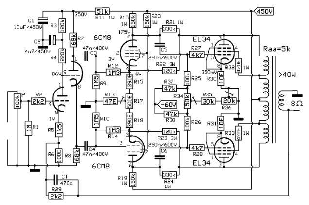
I will reuse these power and output transformers to test a simpler project.
I would like to use the output transformer (specs in attachment) connecting a 8 Ohm load on the 4 Ohm output, in order to work with a 7k Raa load.
What drawbacks do you see in the working conditions of the output transformers by doubling the reflected primary impedance?
What I know is that I will need half the impedance from the output tubes to have the same frequency of the lowpass.
Will I have any other difference? E.G. it is designed to swing less voltage and more current to get the same power, will the different working conditions affect the power capabilities?

Thank you in advance,
Roberto
I would like to use the output transformer (specs in attachment) connecting a 8 Ohm load on the 4 Ohm output, in order to work with a 7k Raa load.
What drawbacks do you see in the working conditions of the output transformers by doubling the reflected primary impedance?
What I know is that I will need half the impedance from the output tubes to have the same frequency of the lowpass.
Will I have any other difference? E.G. it is designed to swing less voltage and more current to get the same power, will the different working conditions affect the power capabilities?
Thank you in advance,
Roberto
Attachments
@baudouin0 thank you, I remember your thread about the 100W amp.
May I ask your help for my post #208 about mismatching the output transformer impedances?
Thank you in advance.
Roberto
May I ask your help for my post #208 about mismatching the output transformer impedances?
Thank you in advance.
Roberto
Your OK to do that it's just reflected back in the primary impedance as you explained. You can draw load lines for the EL34 and many will explain much better how to do this. I'd just try it on LTspice until I get the max power transfer. However, you won't get the twice primary inductance so the bass roll-off will be higher. So if you want to do this start with a high Lp. So adjust L5 for max power before clipping which will give you the best turns ratio you need. II think you will be looking at about 5-7K Raa for Va = 400V.
Last edited:
@baudouin0 thank you again.
For this specific project I would like to keep the cheap transformers I already have bought with that amp and reuse them for an indeed cheap (but very good on simulations) project. I want to try if this could become like "La Vespa" of amplifiers.
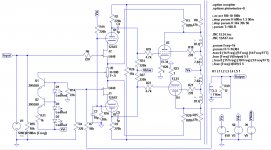
The basic idea comes from an article appeared on Wireless Engineer on 1933, page 413 and following ( https://worldradiohistory.com/UK/Experimental-Wireless/30s/Wireless-Engineer-1933-08-S-OCR.pdf ): scale down the amplified (and inverted in phase) signal, sum the input to it and so obtain a signal that is only the error of the amplification (aka the distortion), then amplify it and apply as feedback.
On simulations I get a Rout of 0.2 Ohm, 1 Wrms @ 0.004% THD and 40 Wrms @ 0.07% THD.
Not tubey anymore? Yep, probably, but then it's just a matter of reducing the Fbk.

I attach the LTSpice file if you want to play with it.
For this specific project I would like to keep the cheap transformers I already have bought with that amp and reuse them for an indeed cheap (but very good on simulations) project. I want to try if this could become like "La Vespa" of amplifiers.
The basic idea comes from an article appeared on Wireless Engineer on 1933, page 413 and following ( https://worldradiohistory.com/UK/Experimental-Wireless/30s/Wireless-Engineer-1933-08-S-OCR.pdf ): scale down the amplified (and inverted in phase) signal, sum the input to it and so obtain a signal that is only the error of the amplification (aka the distortion), then amplify it and apply as feedback.
On simulations I get a Rout of 0.2 Ohm, 1 Wrms @ 0.004% THD and 40 Wrms @ 0.07% THD.
Not tubey anymore? Yep, probably, but then it's just a matter of reducing the Fbk.
I attach the LTSpice file if you want to play with it.
Attachments
I don't think I am adding much to the equation. Nice to see you using ltspice and prototyping. I think Lp is a little low for full 20Hz but that's fine. I don't tend to use JFETS as CCS as they have a wide spread of current they generate from device to device. You may also run into HF stability issues when you add more leakage inductance and primary cap to your transformer model.
Last edited:
Yes, Lp is very low indeed. I would have expected at least 10 times more, but I think this trafo has been done by a guy used to build guitar OPT (the impedance is close to Marshalls, the Lp close to guitar OPTs).
Usually I use the cascoded transistors for CCS, but here I wanted to reduce the BOM to a minimum. I will see how it will goes with the single JFET.
I will for sure check the cascoded too and hear the differencies.
Usually I use the cascoded transistors for CCS, but here I wanted to reduce the BOM to a minimum. I will see how it will goes with the single JFET.
I will for sure check the cascoded too and hear the differencies.
Its more you will get quite a wide spread of currents for different BF256C. OK if you are prototyping.
Besides the low level frequency response being worse, the core will saturate at a higher frequency for the same power output, as your voltage swing will need to be higher into the higher impedance (by 1.4x).
Thank you @baudouin0 and @tikiroo
I was thinking about the CCS, and I know zeners are noisy, but on the tail on a phase splitter the noise should be canceled, am I right?
I was then thinking to use the full 80Vac winding I have available (and a zener instead of the red led) to have an higher impedance on the tail of the LTPI.

At the moment I've removed the feedback circuit from the schematic to focus on this part.
Then, concerning the feedback, I was thinking to use an OPAMP, because I can DCcouple it to the grid of the second triode of the LTPI and avoid a capacitor in the feedback loop. This way should be more stable.
I was thinking about the CCS, and I know zeners are noisy, but on the tail on a phase splitter the noise should be canceled, am I right?
I was then thinking to use the full 80Vac winding I have available (and a zener instead of the red led) to have an higher impedance on the tail of the LTPI.
At the moment I've removed the feedback circuit from the schematic to focus on this part.
Then, concerning the feedback, I was thinking to use an OPAMP, because I can DCcouple it to the grid of the second triode of the LTPI and avoid a capacitor in the feedback loop. This way should be more stable.
You don't need a DC cap in the feedback as both the output and the grid of U8 are at DC ground. the zener use a low voltage one say 5v6 which are much more stable and less noisy. Some spilt R46 and take a current mirror from centre.
I didn't explain it correctly. When I was talking about using the OPAMP for feedback to substitute J1 on schematic at post #212 ( https://www.diyaudio.com/community/attachments/pp-el34-ul-schade-corrdiff_02-jpg.1093253/ ) that I omitted in the last circuit to focus on the simple circuit.
Thanks for the tip on the zener and on R46!
Thanks for the tip on the zener and on R46!

- Home
- Amplifiers
- Tubes / Valves
- improvements on 12AX7 12AT7 EL34 schematic?