Yes, indeed, taking the N Fdbk back to the driver cathode should be much cleaner with more loop gain and less driver Vg1 to K distortion inserted.
With a low gm output tube in the original configuration (so called shunt "Schade"), the output tube grid drive voltage, Vg1, is inserting noticeable distortion in the current Fdbk thru the Fdbk resistor. One way to fix that would be to put a P-chan Mosfet in series with the feedback resistor as a grounded gate stage. That way the current thru the Fdbk resistor (and subsequent Drain current to the output tube grid) will be proportional to plate V minus the AC ground reference at the gate, rather than plate V minus grid drive V.
Another advantage can be derived as well by referencing the gate to B+ instead of Gnd, then Fdbk current is proportional to voltage across the primary. (so B+ ripple removed)
Wavebourn took it one step further by driving the P-chan gate with signal voltage, making the Mosfet the driver itself. I think he had a source resistor to B+ in there too.
What do you make of the distortion results that I got with a mosfet driving this transformer with very little distortion on the primary, but quite a bit of distortion coming out the secondary? Is this just the nature of SE transformers? Would I get better results with a more expensive transformer?
I mean, for all the faults of the circuit I tested, I don't know if I'm going to do much better without a loop around the transformer if the mosfet couldn't do it. The only way to counter that would be anti-phase pre-distortion on the primary side, which may actually be happening here in the areas where this circuit beat the mosfet.
I mean, for all the faults of the circuit I tested, I don't know if I'm going to do much better without a loop around the transformer if the mosfet couldn't do it. The only way to counter that would be anti-phase pre-distortion on the primary side, which may actually be happening here in the areas where this circuit beat the mosfet.
What do you make of the distortion results that I got with a mosfet driving this transformer with very little distortion on the primary, but quite a bit of distortion coming out the secondary?
For the same magnetic flux through the windings (assuming they are wound on the same lamination leg), the signals (other than V to I ratio) should be the same, except for V drop from leakage L and winding R. Magnetizing current, which I usually think of as the main issue with air gapped OTs, should distort the primary V just as much as the secondary V (via tube distortion caused). (low tube output Z needed to fix) Similarly for winding capacitance drawing current.
So leakage L and winding resistance seem to be what's left. Those can be measured to see if they are excessive. If the xfmr is really old, maybe the laminations have worn thru the oxide coatings in places, to cause eddy currents. I guess an L meter with loss detection (ie, R component readout too) could tell if that is an issue (using no load attached to secondary). You probably need a good OT to compare with though.
You might try a high current CCS on the secondary to null the DC, to see if that makes any difference. Then switch over to a non-gapped OT (using the DC CCS current null) to see if any improvement occurs.
Last edited:
For the same magnetic flux through the windings (assuming they are wound on the same lamination leg), the signals (other than V to I ratio) should be the same, except for V drop from leakage L and winding R. Magnetizing current, which I usually think of as the main issue with air gapped OTs, should distort the primary V just as much as the secondary V (via tube distortion caused). (low tube output Z needed to fix) Similarly for winding capacitance drawing current.
So leakage L and winding resistance seem to be what's left. Those can be measured to see if they are excessive. If the xfmr is really old, maybe the laminations have worn thru the oxide coatings in places, to cause eddy currents. I guess an L meter with loss detection (ie, R component readout too) could tell if that is an issue (using no load attached to secondary). You probably need a good OT to compare with though.
You might try a high current CCS on the secondary to null the DC, to see if that makes any difference. Then switch over to a non-gapped OT (using the DC CCS current null) to see if any improvement occurs.
So...I never really got to take a measurement to confirm that my primary voltage waveform was low distortion. I was attempting the measurement when I disconnected the input to the amp and everything broke out into full-power oscillation and some parts literally went up in flames. I elected not to do extensive repairs to take that one last measurement, since I decided that I wasn't going to build that into a real amp.
I just don't think it likely that a mosfet follower would add much distortion, especially this comparatively huge amount of 2nd harmonic. Any reason I might be wrong?
I like the idea of playing around and investigating transformer distortions in general. I've just had much lower distortion results with push-pull amps without feedback around the output transformer in the past. I figured the same could be accomplished in SE with clever circuit design but now I'm wondering. Or maybe it's as simple as ponying up some money and buying a top-quality transformer. I don't have a problem with that, especially if I'm going to go through all the effort of building an amp.
Even with buying top-quality transformers, this hobby is still a lot cheaper than a classic car hobby.
If the primary V is distorted, then OT magnetizing current is likely the issue, since that loads down the tube with a non-linear load. Normally 3rd harmonic magnetizing current is the problem with a non-gapped OT, but a gapped OT with DC offset has 2nd harmonic variation of the permeability and much higher magnetizing current. Low output impedance from the driving device is needed to overcome that, which is not usually a strong case for SE designs.
If the primary V is distorted, then OT magnetizing current is likely the issue, since that loads down the tube with a non-linear load. Normally 3rd harmonic magnetizing current is the problem with a non-gapped OT, but a gapped OT with DC offset has 2nd harmonic variation of the permeability and much higher magnetizing current. Low output impedance from the driving device is needed to overcome that, which is not usually a strong case for SE designs.
Right, but in my earlier experiment I drove the transformer with a mosfet (source follower config) with 460V B+ @~85mA quiescent current. Zout measured on secondary was 0.6 Ohm (0.55 Ohm is due to copper resistance), indicating that the primary was being driven with very low impedance drive. Yet I still saw 0.31% THD at 1W. The tube driving the mosfet was less than .01% THD at that drive level. I'd figure this would be as ideal as things could get in a SE design to meet the magnetizing current demands.
I'll have to do some thinking on how to do some good measurements on this transformer with what I have lying around. I'd like to catch it in the act, so to speak, and vary conditions to figure out how to use it best.
I think this will be my one and only foray into Class A SE tube amps but it has been a pretty fun learning experience so far.
The 2nd harmonic distortion definitely adds a pleasing color to some sounds, particularly plucked strings. However, I can just sense that there is something not-quite-right with a song that is mixing enough sounds together (like bass-heavy electronic music). It probably just takes a certain amount of tone mixing to get to the point that my brain is able to detect the IM products and find them objectionable.
The 2nd harmonic distortion definitely adds a pleasing color to some sounds, particularly plucked strings. However, I can just sense that there is something not-quite-right with a song that is mixing enough sounds together (like bass-heavy electronic music). It probably just takes a certain amount of tone mixing to get to the point that my brain is able to detect the IM products and find them objectionable.
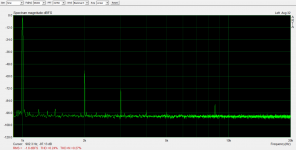
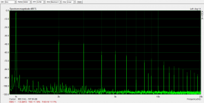
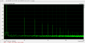
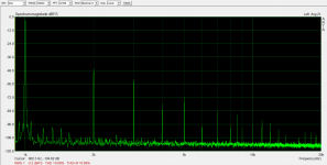
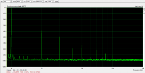
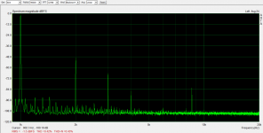
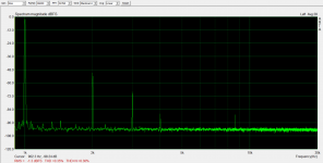
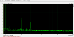
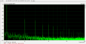
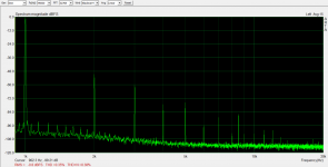
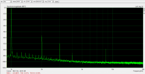
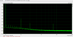
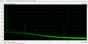
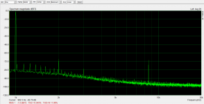
So I finally got to do some primary vs. secondary measurements at 1W, 2W, 5W, and 10W.
At lower levels, distortion is pretty close between primary and secondary. 5W and up, there is significantly more distortion on secondary than primary.
So I don't really know why the mosfet in my earlier experiemental amp couldn't do better than it did at lower power levels. It seems that driving SE transformers is a rough gig. I'm just used to the easy, low distortion in push-pull amps.
Attachments
While I'm always interested in your circuit designs, in this case I think it's even more cool that you did this for your daughter and that the teacher went along with the idea. So I have to ask, how did that part of the project go?
The teacher was really cool and encouraging. I think he was kind of bummed out that his plans for the rest of the year were somewhat ruined by COVID-19 precautions, and this seemed like at least somebody would be building something interesting. I mean the kids still had a mechanical design project they had to do at home but it was with scraps they could find around the house rather than with better quality stuff they would have had access to from school.
So I think the teacher appreciated the extra project from that standpoint and my daughter was able to improve her grade from a previous group project that didn't go that well, as group projects sometimes don't.
The hard thing was that I only had a couple of months to get some fairly complex concepts across. I still don't know if they understood why feedback make things better, for example.
However, I did get to include my other daughter in it as well and they did a good job wiring things up and really did pick good operating points once I walked them through the process of drawing a load line and making sure the swing was symmetrical.
I think the project was successful and rewarding for them, but I don't think it all stuck with them to the degree that they'd be able to do it themselves again without my help. And I don't think they love it quite like I do, but it was pretty fun for all of us to do something together while we were all shut in the house.

I have converted this amp to a pentode input stage and applied the feedback to the input stage cathode. The thread title is no longer accurate as this is series-applied voltage feedback. Why'd I do that rather than try to make a linear tube V-to-I converter to replace the solid state circuit?
I want to apply this to a lower gm output tube later and 100% feedback on that tube won't give me the results I want. I also couldn't figure out a simply way to keep from referencing inputs to negative rails. I like the series feedback to the input stage cathode since it easily avoids that.
My goal in this design was to get a healthy amount of open-loop gain so I could get the distortion to be better than the 100% output stage feedback previously tested in this thread with the op-amp/fet input stage.
First attempt was with a 47k resistor as plate load for the pentode input stage. The result was 1.25% distortion at 1W. Gain of the input stage was only 60. Clearly not enough gain to apply enough feedback...
Second attempt was with a 3.5mA CCS plate load in parallel with 440k. This got me an open-loop gain of ~360 in the input stage. Eerily, the distortion measurements of the complete amp came very close to every measurement of the amp with the op-amp/fet input stage. It really made me think I had some sort of measurement setup issue because it was so close. Then I though about it a bit. The open loop gain of the input stage was almost exactly the gain I was setting in the overall amp (input to plate). This meant all of the gain of the output stage was going to feedback. Makes sense that this would give similar amount of distortion to a 100% feedback configuration around just the output stage. Pretty good but I wanted to do better.
Third attempt was with the 3.5mA CCS plate load in parallel with 1M to reduce current feedback further, but still provide a little bias stability. Open-loop gain was measured at ~560 for that stage.
Distortion results were as follows:
100mW: 0.045%
500mW: 0.1%
1W: 0.14%
2W: 0.21%
5W: 0.35%
10W: 0.51%
Zout: 0.8 Ohm
I learned a couple of things:
1. It's tricky to actually apply more feedback in this configuration. I didn't want to vary the feedback resistor from plate to input cathode, since a lot of voltage/power is seen there. However, when you increase the feedback in the amp by increasing resistance in the input cathode, you end up increasing the current feedback in the input stage by almost as much, causing a corresponding loss of open-loop gain in that stage. When I applied enough additional feedback to halve input sensitivity, I only saw about 10% improvement in distortion. I had to figure out how to get rid of unwanted current feedback in the input stage.
2. CCS load in parallel with a resistor works great to get lots of gain in a small signal pentode and minimize current feedback in an unbypassed cathode resistor. 1M in parallel seems sufficient to get a stable bias point.
Attachments
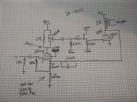
Oh, and I forgot to mention that the mosfet follower can probably be eliminated now. I kept it because this amp is going to get an output tube that will require it, but since I am taking output from the first stage from the source of the CCS mosfet, it shouldn't have trouble driving a 100k resistor.
That would make this a very simple amp to build with one B+ and one bias supply voltage only. A cathode bias version could be very simple indeed.
Another thing I forgot to mention: The input stage loves to oscillate when input is left floating. It does it with or without output tube installed. I put a 10k resistor on the input, which stops that from happening. I haven't thought of a better solution. Also, I have a 1k grid stopper on the input stage which I didn't bother showing on the schematic.
I swapped out the 6EW6 input tube for a 6BN11 last night. My 6EW6s tested good but I did notice that they required higher screen voltages to get Vg=0 up where it should be. The did not match the datasheet characteristics, in other words. They were both used tubes pulled from equipment.
My 6BN11 is NOS and offers characteristics very similar to the datasheet. I did a simple gain test and I was getting a gain of over 700, whereas the 6EW6s were giving me ~550 in the same circuit. The datasheets indicated that these tubes should have pretty much identical characteristics, which mine obviously do not.
I also really like the looks of the 6BN11 as well. Both tube types have a very open plate structure but all of my 6EW6s have a smoked glass coating on the inside that hides it (which probably improves performance somehow but I'll be honest, I'm designing with tubes because they look cool, seeing hot cathodes and grid wires is a plus).
Attachments
Last edited:
- Status
- This old topic is closed. If you want to reopen this topic, contact a moderator using the "Report Post" button.
- Home
- Amplifiers
- Tubes / Valves
- Shunt Feedback 6384 SE Amp