The gain added in the feedback loop presumably uses active devices, so adds it's own distortion. It would have to be perfect (0 distortion) to improve the net result beyond the distortion of the full loop corrected by the now higher loop gain. A Spice gain block would of course be perfect (up to the accuracy of the floating point math at least).
Adding gain in an inner N feedback loop does get used occasionally (very occasionally) to fix badly distorting stages, but an outer resistor controlled global loop is used to finish up the job for very low distortion.
Adding gain in an inner N feedback loop does get used occasionally (very occasionally) to fix badly distorting stages, but an outer resistor controlled global loop is used to finish up the job for very low distortion.
Last edited:
Hmmm, I don't think it works the way you describe. You're referring to the type of feedback distortion that allows a super triode to function the way it does? The output signal is still being controlled by an opamp, so there is nothing else in effective feedback path other than the feedback resistors. The feedback works in the same way as a composite opamp circuit but it's a lot more stable and has a S**t ton more gain.
Unless I'm stupid and I don't understand what you are saying.
Unless I'm stupid and I don't understand what you are saying.
Last edited:
smoking-amp is our resident tube circuit guru, take time to understand what he is saying..
touch bases with PRR if he will reply he can give you solid advice..
touch bases with PRR if he will reply he can give you solid advice..
When I worked in the phone group at Motorola there were the big three players in the phone market, Nokia, Ericsson and Motorola. It stayed that way for years, with Nokia in the #1 spot, Motorola and Ericsson flipping back and forth for #2 and #3.
Along came a new player in the market, Apple with their iPhone.
Within a month or two we had one, and we ripped it apart and analyzed how it was made, and all things technical about it. From a technical perspective AND a manufacturing perspective it was by far inferior to the mid range and high end of anything sold by the big three.
Fast forward say 20 years, and we all know how that played out.....All of the big three players, are gone, kaput, out of the phone business. The Motorola name is now owned by Lenovo, a Chinese computer company, Someone is also selling phones under the Nokia brand, but I don't know who. Sony grabbed up Ericsson's phone business, but failed to do much with it.
The lesson to be learned here.....
The CUSTOMERS don't give a squat about the TECHNICAL aspects or MANUFACTRUABILITY of the product, they only care about WHAT the product can do for them, and that it does it BETTER, or at least DIFFERENTLY than the other players in the market. Differently can become trendy, and trendy is what Apple wants.
Very few customers will care if your amp can make -120 db of distortion or -200 dB of distortion, and absolutely NONE of them could hear the difference, but many will BELIEVE they can.
Most "audiophiles" rely on word of mouth, or worse, magazine or web site reviews to convince them that one product is better for THEM than another.
A few actually know how to read specs.
It does not matter if your amp really does have -200 dB THD, if it truly does -100, then you have something, assuming that IMD doesn't suck.
They WILL care if it blows up at 60 watts if you claim it will do 100.....In fact they will care and the product will fail in the marketplace if it blows up at all from ANY possible user applicable misuse.
One of the reasons that it takes me forever to get a product ready to be called a Tubelab, is my ridiculous and extreme testing. That comes from designing products at Motorola where a police or fire officer's life may depend on that radio working.
All of my amps must be able to eat my guitar playing when driven at any level up to 10 to 20 dB into clipping for long periods of time. They should be able to be left on at idle forever (serious stress for a class A amp). it should eat low and high line voltages without damage......
Come up with a bulletproof design, test it yourself with the equipment you have, it's obviously better than mine, so it's a place to start. Get it out there even if you have to give the first few away. Make some YouTube videos, and maybe a web site. If it is truly a breakthrough (or sufficiently different) product, it will be discovered. Then get THEM to test it for you.
that is all true, when someone wants to borrow my amp for home audition, i oblige, sometimes i get lucky, i did sold, but other times they come back with feedbacks, those feedbacks i consider as a gift and learn from it..
one thing i learned, selling amps unless on a massive scale with tight margins can not get you anywhere...
so today i do conduct teach-ins and build outs, the little money that comes is good enough, i have no reason to complain..
one thing i learned, selling amps unless on a massive scale with tight margins can not get you anywhere...
so today i do conduct teach-ins and build outs, the little money that comes is good enough, i have no reason to complain..
So essentially what I did during the opamp test was add the circuit in question into the feedback loop of the opamp and used the opamp as the output device.
Well, that sounds like what I was describing, adding gain into the feedback path. If the gain is accurate to -290 dB (dist.) it would work.
The fundamental way it works is by adding an absolutely bonkers amount of gain into the main feedback loop without becoming unstable. The stability of it is really the main specialty here.
Unclear here where the gain is being put.
You could put an Op Amp, or whatever, into the forward path to increase the gain enormously, and that should work to reduce the distortion big time as you state, since the N Fdbk resistors would be setting the forward gain (assumed perfectly accurate versus signal). (also assuming near perfect error subtraction) The usual problem with enormous forward gain is phase/stability. All parts of the forward path would have to be extremely optimized for bandwidth to get -290 dB distortion results. Maybe in Spice, hard to believe in practice. At least stability is easy to test for. You don't need $$$ equipment for that.
-------------------------------------------------------------------------------------
On testing dist. at -290 dB level:
A 32 bit sound card would (ideally) give 2.3 parts in 10 to the 10th precision. And -290 dB would be 3 parts in 10 to the 15th precision.
So one needs 100,000 times better precision than the 32 bit can provide. In theory, one could attenuate the output of the D/A by 100,000 to get a step size that small. So a macro ramp signal would be used to sweep across the test voltage range (very slowly, in fact using discrete steps, so constant during each point test) with the tiny attenuated D/A signal added to it. The D/A would be stepped in a continuous ramp of 100,000 micro steps at each test point (test points along the macro ramp), and the output of the Amp then is sent to a differentiator, which would convert the micro ramp into a constant voltage (at that test point). The sound card A/D would then read the constant V from the differentiator to plot on the gain graph or table (versus the macro ramp V). I think that could work (in theory at least). Since that then gives 2.3 x 10 to 10th accuracy of gain around the nominal expected gain. (we have removed the bigger 10 to 15th number in the nominal gain factor. We cannot say what the gain is to precisely 10 to 15th accuracy, but we can say what the gain variation from the nominal is at 10 to 10th accuracy.
Last edited:
The lesson to be learned here.....
The CUSTOMERS don't give a squat about the TECHNICAL aspects or MANUFACTRUABILITY of the product, they only care about WHAT the product can do for them, and that it does it BETTER, or at least DIFFERENTLY than the other players in the market.
I agree that no one can hear such distortions. I originally designed it so I could control the distortions during my R&D of trying to find and control the source of "euphonic" sound without having to worry about unwanted distortions in the system.
I ended up veering off them that objective once I realized how potent the anti distortion circuit actually was.
In terms of an end-product. The prototype I'm working on now costs like $50 to make assuming the parts and PCBs are ordered in bulk of 1000. The intent is for it to be a $150 25W balanced class A amp that can fit in your hand and produce "unmeasurable" distortion into any load within spec. That seems like a good deal to me compared to existing stuff.
I've confirmed the other specs but the "unmeasurable" distortion part is not something I can say without authoritative verification though. The output voltage will be equal to the input voltage so direct couple to dacs is possible.
I built it with thermal and current throttling but there is no relay on the output which is the part I'm not particularly pleased with. I'm assuming that's a bad idea?
I have a handful of audiophile fans in New York. They are a gift as I NEEDED the feedback. My stuff always beats out their fancy jillion dollar stuff in shootouts except for my DAC creation which was indistinguishable from their best dac but mine is cheap to make so it fits perfectly into a $300 amp/dac combo rather than spending thousands on a dac that sounds the same.n.
Get it out there even if you have to give the first few away. Make some YouTube videos, and maybe a web site. If it is truly a breakthrough (or sufficiently different) product, it will be discovered. Then get THEM to test it for you.
They've already arranged to buy whatever I make when it's ready for general use but they lack the reach I need and my current prototype iteration is not ready for prime time, I need one more iteration and it's like a $700 expense so I will need to wait quite some time before I can attempt it.
Just imagine a composite opamp. The feedback is functionally the same, just with different stuff in it.Unclear here where the gain is being put.
Yes, this is the most important part that makes my circuit unique. The ability to be stable in the face of so much gain.The usual problem with enormous forward gain is phase/stability. .
The closed loop bandwidth is pretty high, the simulated -3db down point is 108Mhz which is insane I am highly highly skeptical of that. I wouldn't be entirely surprised if it was true though.
In any case the compensation I use is fairly minimal in any particular portion of the circuit.
Last edited:
the product will fail in the marketplace if it blows up at all from ANY possible user applicable misuse.
One of the reasons that it takes me forever to get a product ready to be called a Tubelab, is my ridiculous and extreme testing. .
Exactly my own approach, which comes not from mobile radios, but engines for motorsport, which has lots of connections with trying to keep people alive doing dangerous things.
In that example, (adopted by Cosworth decades ago), you first stick the thing on the dyno and try your hardest to blow it up. (You will usually succeed if you try hard enough).
Once it has blown itself to smithereens, melted or generally grenaded itself you sweep up the fragments and analyse what made it do that.
OT;-
(A friend of mine managed to get a Peugeot 205 petrol engine with a diesel crank to run reliably at 10 000rpm using exactly this approach,- solving the main engineering challenges one by one)
That is how you make a world famous product that is literally bomb proof, and it's how they are supposed to test aircraft (trying to crash it).
The drama happens (as Boeing so beautifully illustrated at enormous cost) is when you try to evaluate your customer on the product, and it doesn't fly.
Drag the same methods into amplifiers, - the dyno being dummy loads, surrounded by instruments, try to blow it up.
I see all those commercial "hi end"amps melting to the point I daren't try any more.
That's why mine don't!
Great quote:-
If you think developing and testing an aircraft + getting certification is expensive, just try having an accident!
Actually that was quite funny! 😀when you try to evaluate your customer on the product, and it doesn't fly.
I actually meant try to evaluate the product on the customer not the other way round. 🙂
Spice results for me have been pretty accurate to what I've seen on the bench as well.
The research department at Motorola where I worked for the last 11 years of my career morphed from a circuit design center into an IC design center during that time. 99% of all IC design work relies heavily on the Spice based simulator. In that case the simulator MUST have exquisitely accurate models of every aspect of each microgeometry in the IC's process. The vendor that is fabricating your silicon will provide these models, and they are characterized and updated constantly.
This is not always the case in the solid state world, especially when several vendors using different wafer fabs are all selling parts with the same type number on them, and not all are even built on the same process geometry.
This is NEVER the case in the vacuum tube world, since most of the models we have were made by enthusiasts from a few samples of vacuum tubes long after production ceased. Results vary from "not bad" to "useless" when the tube is used as a "normal" amplifier in a typical circuit where things like grid current don't matter. Results when the tube is used outside its original design modes (like screen grid drive) may not even converge, yet the circuit works when built. THD numbers generated by LTspice on a vacuum tube circuit are often "optimistic." I still use LTspice to tell me if an idea has merit, but don't trust the results until the design has been built and tested.
which comes not from mobile radios, but engines for motorsport
I did the same thing. Unfortunately well built auto engines cost quite a bit more than an audio amp, so you try not to blow up too many.
This forum is good for communicating with other people, and learning from their mistakes.....IE, let someone else blow up parts, so you know what NOT to do.
In the 1980's when I was racing turbocharged Dodges I learned a lot from a man named Carroll Shelby. I read every one of his books on the Chrysler 2.2L engine, talked to him and a couple of his car and engine builders on the phone, and purchased a lot of "blow proof" parts from him.....None of his parts ever broke, but they weren't cheap.
the dyno being dummy loads, surrounded by instruments, try to blow it up.
Look at it this way.....engine RPM is analogous to open circuit output voltage. Engine torque is analogous to the current being driven into the load by the device under test. Power output is the combined effect of the available output voltage (or RPM) being able to push enough current (or torque) into the load cell to make a certain power level without blowing up, or loosing too much efficiency in the process.
We can reduce the load impedance in the same way that you would turn up the resistance in the dyno's load cell to keep the RPM constant and measure torque. One can make the same type of "power" curves seen in dyno testing an engine, and .....1 HP = 746 watts.
Shelby told me that all of the 2.2L turbo engines in factory Shelby Chargers with warrantees were limited by the ECU to 175 Ft LBS of torque so that the small transaxle in the L body cars would survive.
I got him to make me an ECU with the torque (turbo boost) limit removed and the RPM limiter bumped up to 7200 RPM. In 5 years of racing and street driving I had to rebuild the transaxle 4 times.
Note, the transaxle is analogous to the OPT in a tube amp. High RPM (voltage) low torque (current) goes in and low RPM high torque comes out.
Look at it this way.....engine RPM is analogous to open circuit output voltage. Engine torque is analogous to the current being driven into the load by the device under test. Power output is the combined effect of the available output voltage (or RPM) being able to push enough current (or torque) into the load cell to make a certain power level without blowing up, or loosing too much efficiency in the process.
We can reduce the load impedance in the same way that you would turn up the resistance in the dyno's load cell to keep the RPM constant and measure torque. One can make the same type of "power" curves seen in dyno testing an engine, and .....1 HP = 746 watts.
Note, the transaxle is analogous to the OPT in a tube amp. High RPM (voltage) low torque (current) goes in and low RPM high torque comes out.
100% agree with that. 😀
I just haven't found an electrical equivalent of brakes and suspension although critical resonant phenomena and damping are vital things to understand.
What is funnier is the extraordinary number of people involved in interesting electronics who are also true "petrol heads".
I could almost immediately work out if some so called "audio guru" is any good by the position of the accelerator pedal and their relationship to "fear".
Most of the really good audio people I know are old car nuts, and rebels.
I can't fathom out why! 🙂
when you try to evaluate your customer on the product, and it doesn't fly.
Hmmm.... A test product for customers! Put in a small extra circuit that secretly puts in various types of .001%, .01%, .1%, and 1% distortions with a selector switch, and ask them to evaluate what "optimization" position sounds the best to them, and rank them in order. We'll soon find out more about those "golden ear" audiophiles. 😀
If it converges at all, the results could even be valuable information for future product design.
---------------------------------------------------------
On testing the OP's low distortion Amp, why not just use the technique that the Op Amp Mfr's use to test their Op Amps? Just put a low value resistor across the + and - inputs (or high R in series with the input diff stage emitters) to kill the gain by some prescribed amount, and test the degraded Amp with a sound card FFT analysis. Then add back in the dBs of gain degrading.
----------------------------------------------------------
A discrete Op Amp with super low distortion on a small PC board might be a sell-able product. Some tough competition from the latest integrated Op Amps however.
Yeah I had tons of experiments like this planned before I veered off to develop my anti distortion circuit.Hmmm.... A test product for customers! Put in a small extra circuit that secretly puts in various types of .001%, .01%, .1%, and 1% distortions with a selector switch, and ask them to evaluate what "optimization" position sounds the best to them, and rank them in order. We'll soon find out more about those "golden ear" audiophiles.
If it converges at all, the results could even be valuable information for future product design.
Most of them related to different types of amp and dac distortion but there's one in particular I want to try.
The step of the process go something like this
Take 2 high quality ribbon mics and put them ear width apart. Optimally speaking you'd want a dummy head with your personalized ear structure.
Step 1: Have a sound source create a noise that is repeatable, record it and store it on a file for later playback through the dac/amp.
Step 2: Play the noise again but this time the mic will drive the amp directly using an I/V converter.
No mic transformers or any gunk in between, just an electrical signal picked up from the mic direct driven to the amp configured as an I/V stage.
Step 3: listen to the sound source in real life from the location of the "dummy head".
So if you Play the recorded sound back through the dac/amp using the first method, then play it using just the amp with the second method, and finally play it in free space using the last method you would be able to discern what, if any part of the chain is imperfect and you would be able to record the wave-form on each one to be able to see where the differences are to begin trying to solve the problem.
Most iterations of my design weren't compatible with that method due to the unique configuration I had to use but I've since altered the way I configure it so that could actually work. I'm sure the results will be disregarded as usual though.On testing the OP's low distortion Amp, why not just use the technique that the Op Amp Mfr's use to test their Op Amps? Just put a low value resistor across the + and - inputs (or high R in series with the input diff stage emitters) to kill the gain by some prescribed amount, and test the degraded Amp with a sound card FFT analysis. Then add back in the dBs of gain degrading.
Yes I built such a thing, in images I posted earlier the small PCB attached the bottom with dip connectors is the SMD version of my circuit.A discrete Op Amp with super low distortion on a small PC board might be a sell-able product. Some tough competition from the latest integrated Op Amps however.
My problem is it's gunna get stolen if I release it without protection, but it's gunna get copied anyway so I'm just gunna try to get a GB of 1000 units (to get the cost down to my $150 goal) using kickstarter or something.
Preferably release my dac and headphone design at the same time for a triple whammy.
But that's just a dream at the moment.
Suspension can be modeled as a complex LCR circuit from what I remember in my Strengths and Materials course in college.
IIRC, all mechanical systems can be modeled as equivalent electrical systems.
I no longer have a clue how to model them.
IIRC, all mechanical systems can be modeled as equivalent electrical systems.
I no longer have a clue how to model them.
Preferably release my dac and headphone design at the same time for a triple whammy.
A USB dac and headphone amp might be worth pursuing first.
jeff
It's essentially the same thing.A USB dac and headphone amp might be worth pursuing first.
jeff
The combined price of sale will be about $300 which is about the cost of a low end "hi-fi" amp/dac headphone setup.They are about the size of such a setup as well.
Except my dac has already matched or beaten the multi-thousand dollar stuff and my amp can drive full sized speakers to 25W.
Last edited:
Suspension can be modeled as a complex LCR circuit from what I remember in my Strengths and Materials course in college.
IIRC, all mechanical systems can be modeled as equivalent electrical systems.
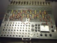
Heatkit tube Analog Computer: (notice all the tubes for the Op Amps along the top of the device.)
File:Heath Electronic Analog Computer at CHM.jpg - Wikimedia Commons
With -290 dB distortion Op Amps, you could give digital simulations some competition. Single precision floating point is not that accurate.
Attachments
Last edited:
Nevermind I take it back the existing version still has a configuration quirk that renders that method unusable.Most iterations of my design weren't compatible with that method due to the unique configuration I had to use but I've since altered the way I configure it so that could actually work. I'm sure the results will be disregarded as usual though.
Now that I think about it I recall that I did build a version that was able to use that technique in the other thread and posted the results, it was unable to produce distortion low enough to see when the circuit gain was set anywhere close to max. I did tons of tests over there showing the results but I don't think anyone kept cohesive track of them since they were spread out over so many pages.
The -290db distortion number was never my official claim, The mods just changed the title of thread and I got massively misunderstood while trying to explain my situation.With -290 dB distortion Op Amps
-290db was the conclusion of the extrapolation I came to when using the opamp method I described earlier. But it was discussed that the noise floor made the measurement inaccurate.
The true 1k distortion, especially on my greatly improved modern version should theoretically be much much better if spice is to be believed to any reasonable degree. It looks like it's touching into -500db range but spice wont render it so I can't tell. There's also the fact that the distortion goes under the noise floor at a small percentage of the maximum gain during my experiments so unless the gain somehow stops working below the noise floor for mysterious reasons it seems safe to assume it keeps on going. But like I said, my word is not enough, I need someone respectable to do the tests before I can claim anything.
Last edited:
A test product for customers! Put in a small extra circuit that secretly puts in various types of .001%, .01%, .1%, and 1% distortions with a selector switch, and ask them to evaluate what "optimization" position sounds the best to them, and rank them in order.
We'll soon find out more about those "golden ear" audiophiles. 😀
If it converges at all, .
I already did that.
I love blind tests.
The golden ears people (that put little blocks under the speaker wires cos they sound better if they don't lie on the carpet, elaborate power conditioners, bespoke speaker wires of all imagineable shapes and sizes...special DAC...et al)..
I blind tested them for 24bit, 16bit, and mp3 high rate, 3 versions of the same live recording of ours.
They all preferred the mp3 version 🙄
I tested numerous people's hearing, inc very disturbingly some young people under 13-14.
The kids were going deaf in a specific spectral range (thanks to digital music), and practically nobody was able to tell when an uncompressed recording HAD actually hit level -1dB.
They all said the whole level was recorded too quiet....
My estimation of those "audiophile golden ears" is now so pessimistic I start to expect the worst.
Last week a guy who claims "he is the best in the country", treated me to a TERRIBLE sounding system, where he couldn't even tell there was a severe reflection node from the ceiling.
I moved the giant speakers fwd 4-5" at which point it vanished, but they are/were using this to demo to their "ultra hi end" customers!
It was unbearable, and it had really significant colouring and bass attenuation.
The centre mid range speaker was so desperately shouty, I had to move out of the way, cos it was making my ear ring and go temporarily deaf, + they insisted on the best resolution recording they had was 44.1-16 **!
One of their top of the line DAC costs wait for it:-
125 000 USD!!! 😱
With stuff/people like this I don't think there's any hope whatsoever for doing stuff properly, least of all as the max dynamic range of any system or source material doesn't exceed 60dB, and 16 bit truncates the reverb anyhow**.
- Home
- Amplifiers
- Tubes / Valves
- 50W super triodes and stuff