T
The definition of REALLY HARD scales with the run rate.
One stupid mistake on an automated line cranking out 10,000 cell phones per shift will make for a lot of scrap.....
Yep, it's ok for a 10USD phone but a whole different ball game, if you churn out
50 000 crankshafts ground or balanced badly, or say one faulty fan blade weld in a complex aero engine.
The colateral damage is simply awesome when one relatively small component fuels a chain of different far more complicated more expensive dependencies and then results in 1000s of warranty claims with law suits appended.
It's that and really disgusting quality control, & lax suppliers, that bankrupted the entire UK motor industry.
It's not exactly doing wonders for Rolls Royce either right now.
Heads roll......

Yep, it's ok for a 10USD phone
Rolled product cost was still about $100 USD at the time (late 90's). The phone had two PC boards, I think the main board scrap level cost was around $30 each. Rework cost depended on where, and how many wrong parts were placed.....reworked products are NEVER as good as those that were correctly built the first time.
An industrial engineer decided to replace a whole line of the typical SMD pick and place machines with this "gang placer" which was huge and shook the whole factory when it ran. There were three (I think) heads. Two were being automatically filled with parts while the third placed them on the board, resulting in a 3 X throughput improvement, and less people running the line......another brilliant idea on paper, or in pretty Powerpoint presentations to management, but after 6 months of constant screw ups, the big expensive machine and the industrial engineer were gone.
The cost of poor quality can be expensive.....in $$$ and sometimes human lives.
a whole different ball game, if you churn out 50 000 crankshafts ground or balanced badly
Or fail to consider all possible modes of failure.....Some of us older car guys remember the nylon toothed timing chain sprockets that GM sprung on us around 1970, and other manufacturers followed. They all failed within 3 or 4 years......and the Chevy Vega aluminum engine with aluminum cylinders, no cast iron sleeves. Even a dummy can see what cast iron rings will do aluminum cylinder walls.....Most of those engines were replaced with iron blocks under warranty.....if the body didn't rust off the car first.
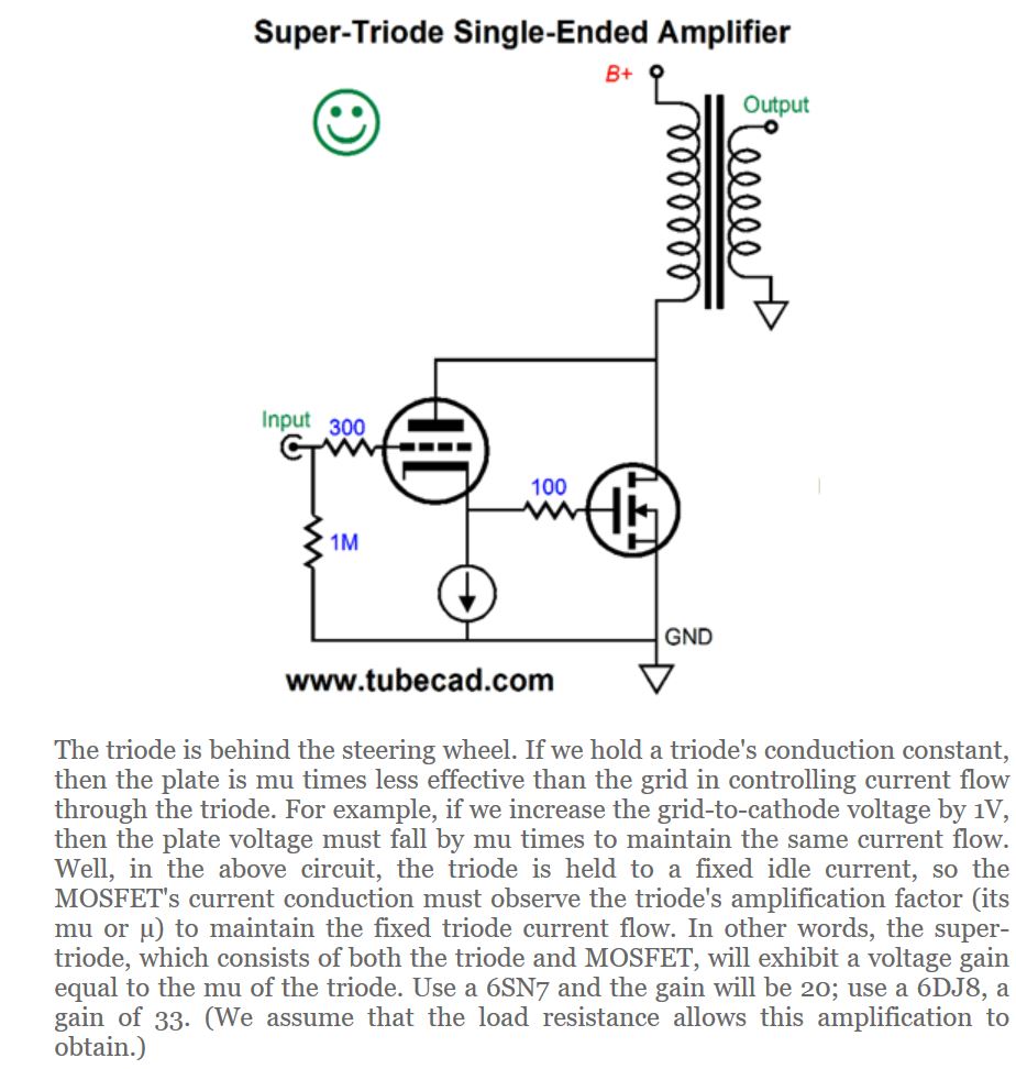
There have been a few attempts to demonstrate the supertriode topology (including from me) but there seems to be a distinct lack of interest. I have built a 50W push-pull version. I think it sounds great but I built it for my own interest and enjoyment and don't really care what others think.I thought 0.25% distortion (mostly second and third) at 36 watts with no global negative feedback was pretty good, output impedance 3 ohms.
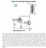
I found it difficult to follow the circuit you posted, it was laid out in an unusual way. Can you please explain how each part works? I've posted it again here for reference.
Okay fine, I'll give the thread one more chance.No kidding.
Working simulation? Really? More like a back of the napkin scribble only using a PC.
Similarly impressed with the pcb layout.
But it's the thought that counts 😀
Agreed the PCB looks like garbage, I typically like to minimize trace distances at the expense of an aesthetic layout. Unwanted parasitics are not fun.
Instead of trash talking people could (gasp) actually give constructive feedback. Whoah, new concept, I know.
The schematic looks perfectly readable to my eyes, not sure what to say there.

The current source at the top sets the total current. The opamp applies the reference voltage to the cathode which applies a constant current across the cathode resistor.
It does this by making the output mosfet react to the cathode voltage, applying the transfer characteristics of the triode to the output of the mosfet in order to ensure the AC voltage at the cathode = 0v.
The potentiometer adjusts the AC gain of the mosfet to allow the tube to start sharing the load current which increases the output impedance up to the RP of the tube.
As shown earlier it does a good job at perfectly replicated the harmonics of the triode under load.
There's a number of other ways to configure the circuit I but this is the one I like the most (so far).
The main thing I don't like is that the current sharing through the 6sn7 maxes out at about 1ma p-p, but I guess that's expected when it's got a 7k RP driving a low impedance load. It's difficult to use it functionally without having the triode work under ideal or near ideal conditions.
A cathode follower version would allow for greater current sharing and therefore greater "distortion" but cathode followers don't excite me very much.
One of the things I like about the plate output concept is the relative voltage output is the inverse of the load impedance so it equalizes the load impedance to some degree. Maximizing this trait would require some more thought, maybe an impedance multiplier is in order.
Last edited:
I don't see any feedback path to make sure the Mosfet is actually putting out current proportional to the tube current. With a bipolar and a Mosfet in series at the output, it would like at least a source resistor to get close to linear response without the N Fdbk monitor. Fdbk would be even better.
The tube current is stable if the mosfet feedback loop is fully engaged. The mosfet reacts to the voltage at the cathode, not the current.I don't see any feedback path to make sure the Mosfet is actually putting out current proportional to the tube current. With a bipolar and a Mosfet in series at the output, it would like at least a source resistor to get close to linear response without the N Fdbk monitor. Fdbk would be even better.
If the pot is turned all the way down there is no feedback and the mosfet does nothing at AC. The tube drives the load completely.
If the pot is turned all the way up the mosfet ensures a stable current at the cathode, in order to do this it must ensure that there is no voltage variation at the cathode. In order for that to happen the output voltage must be exactly the same as what the tube would have produced on its own.
Therefore the tube characteristics are transferred to the solid state portion of the circuit.
Of course it can be somewhere in between where the tube and the mosfet are working together which means a variable output impedance and variable tube loading.
The bipolar is only there to allow the opamp to control the mosfet which functioning on a separate and much higher (relatively) voltage supply in order to keep the dissipation in check given the class A nature of the circuit, hence the 25v supply at its source.
A feedback resistor at the mosfet would only serve to reduce the loop gain.
Last edited:
mosfets do indeed react to voltage at tube cathodes, but the inter-electrode capacitances required current to charge/discharge those capacitors....
to say voltage only not current will be missing it imho..
to say voltage only not current will be missing it imho..
how do you justify the complexity of your design?
Nelson Pass designs are simple and yet deliver the goods,
you used a cathode follower to drive the input of an op amp with a gain of 10, and then drive a common emitter amp to drive the gate of a mosfet...
the op amp gain times the common cathode gain is a lot, you you really need that?
Nelson Pass designs are simple and yet deliver the goods,
you used a cathode follower to drive the input of an op amp with a gain of 10, and then drive a common emitter amp to drive the gate of a mosfet...
the op amp gain times the common cathode gain is a lot, you you really need that?
Last edited:
Oh, OK.
So the tube is running constant current. There will be very low tube distortion in that case. You may not hear much illusive "tube sound" in that case. (2nd harmonic mainly)
So the tube is running constant current. There will be very low tube distortion in that case. You may not hear much illusive "tube sound" in that case. (2nd harmonic mainly)
mosfets do indeed react to voltage at tube cathodes, but the inter-electrode capacitances required current to charge/discharge those capacitors....
to say voltage only not current will be missing it imho..
Could you elaborate on what capacitance you are referring to?
how do you justify the complexity of your design?
Hmmm. Seems like a simple circuit to me. I could build this in on a breadboard in 30min if I had the parts.
Just depends on what your design goals are.Nelson Pass designs are simple and yet deliver the goods,
Nelson's designs are simple which leaves it open to flaws and unsolved issues.
These "issues" may or may not be issues at all when it comes to the end result.
It really just depends on what you're trying to do.
I could make a "ZEN"-like "triode" with transistors that have curves like ones I showed at the bottom of my first post and just drive at several amps and vualá, a "super" triode with only a couple parts. Well, probably more than a couple. I'd want to have parts to eliminate offset for direct drive and probably do a handful of other things to optimize the performance.
I'm not convinced that tube curves cause tube sound or even that tube sound even exists so I opted out of that particular design.
The design goal of most of my designs is to simply "solve all the problems". Even the tiny and abstract things no one considers. Since we don't know what officially causes good sound it's better to take every minute thing into account. At least that's the way I look at it.
If I find out that tubes can actually do something positive to the sound then I can exploit the characteristics that cause it and use that to design a "euphonic" amplifier, probably without even needing tubes, that's the purpose of the super triode to me. A stepping stone to a greater purpose.
It's actually a gain of 100. I'd probably make it a gain of 1000 because an open circuit here is ideally what we want if the gain is fully engaged.you used a cathode follower to drive the input of an op amp with a gain of 10, and then drive a common emitter amp to drive the gate of a mosfet...
the op amp gain times the common cathode gain is a lot, you you really need that?
The bipolar transistor is only there to boost the voltage of the opamp, the potential gain added from it is an unintended bonus.
You could just cap couple directly from the cathode to the mosfet and ignore the opamp and all that stuff but the feedback in this circuits needs to be high in order to have complete control over the cathode. Plus if the point is for it to sound like a tube then why risk it and have a weak feedback loop to begin with? Just do it right the first time.
In this particular circuit since we are using the tube as an amplifier instead of a cathode follower any voltage variation at the cathode is going to have a large effect on the output impedance. Opamp levels of gain are needed here to ensure pure DC is on the cathode when gain is fully engaged.
Yes, the current becomes less constant as you adjust the gain pot and let the tube share more current.Oh, OK.
So the tube is running constant current. There will be very low tube distortion in that case. You may not hear much illusive "tube sound" in that case. (2nd harmonic mainly)
The problem here in this particular case as I noted earlier is the plate resistance is high so there's no scenario where it will have a large amount of current variation regardless of how much of the load it is driving, if you let the tube drive the whole load then the output impedance will just becomes so high that the output voltage is be too low to cause much current variation.
In a manner of speaking the solid state part of the circuit is just an impedance multiplier that varies the impedance that the triode sees from the load between the load impedance and "infinity".
If you say that current variation is the cause of tube sound then maybe I should use a low RP tube like the 6c33c, an RP of like 280 ohms.
That actually has the bonus of being a cool looking tube.
I don't know how 6c33cs sound so idk you tell me.
Or perhaps I need to alter strategies and go with a cathode follower version after all.
Something like this but with more adjust-ability and a resistor load instead of a current source.

Thoughts? I'm kinda liking the 6c33c idea. Only a gain of 2.7 though.
Last edited:
Tube cathode followers don't generally get rave reviews for sound, may not be the best place to start.
For your SS "tube" curves in post #1, I guess those were some Mosfets?
Power tubes typically conform to square law, V to I, over a moderate range, similar to Mosfets.
For your SS "tube" curves in post #1, I guess those were some Mosfets?
Power tubes typically conform to square law, V to I, over a moderate range, similar to Mosfets.
Last edited:
between your super triode and the gate of your mosfet, there is an op-amp and a common emitter transistor amplifier, too much gain, what were you thinking?
reffer to the datasheets of the mosfet you are using...aside from datasheet capacitance, there are also stray capacitance because of your layouts..
you are correct, tube curves are what the designers use to choose a linear operating point consistent with their chosen output swing and slew rates, tube sounds is how you run your tube....it is called "voicing"....
Could you elaborate on what capacitance you are referring to?
reffer to the datasheets of the mosfet you are using...aside from datasheet capacitance, there are also stray capacitance because of your layouts..
I'm not convinced that tube curves cause tube sound or even that tube sound even exists so I opted out of that particular design.
you are correct, tube curves are what the designers use to choose a linear operating point consistent with their chosen output swing and slew rates, tube sounds is how you run your tube....it is called "voicing"....
Last edited:
That's been my experience as well. If you agree then I won't bother.Tube cathode followers don't generally get rave reviews for sound, may not be the best place to start.
It was a mix of jfet, mosfet, and bipolars, configured to work like triodes.For your SS "tube" curves in post #1, I guess those were some Mosfets?
I did some simming with 6c33c triodes configured in the amplification configuration and they still have too high an impedance to produce meaningful current swing during their operation.
The only good way I can think of to make the triode produce current swings in a way that doesn't defeat the purpose in some way is to forgoe voltage swing in exchange for current swing.
Here's a crude concept example

Or I could just do this and make the plate work under constant voltage for the same effect.

The issue with a super triode letting the triode function under variable current and voltage in a SET amplification configuration is that there is nothing for the feedback to latch on to.
Unless I just stick to the first idea and run more voltage swing into the triode so it produces more voltage despite its high RP when taking on more of the load. That's one way of brute force solving the issue I suppose, but the gain has to come from somewhere.
Hmmmmmm.
I've already explained this thoroughly in my previous response to you. It is necessary for multiple reasons. Also there is no such thing as "too much" gain in this schenario, it can only be a good thing.between your super triode and the gate of your mosfet, there is an op-amp and a common emitter transistor amplifier, too much gain, what were you thinking?
The opamp drives that capacitance. It's irrelevant to the operation.reffer to the datasheets of the mosfet you are using...aside from datasheet capacitance
Could you elaborate?there are also stray capacitance because of your layouts..
And how does one run a tube for tube sound?tube sounds is how you run your tube....it is called "voicing"....
Last edited:
Yes it was all that gain that I was wondering about. Below are a couple of screenshots from Tubecad.com explaining the basic premise then fleshing out a SE DC coupled supertriode that does not have the extra gain between the cathode and gate. The point is to make a compound device that has the same mu as the tube but much higher transconductance and much lower rp.
I'll do my own sim of your circuit hellokitty, it will help me understand better.

I'll do my own sim of your circuit hellokitty, it will help me understand better.
Attachments
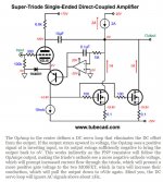
Mine performs better and doesn't have anything in between the triode and the load. A true direct coupling.Yes it was all that gain that I was wondering about. Below are a couple of screenshots from Tubecad.com explaining the basic premise then fleshing out a SE DC coupled supertriode that does not have the extra gain between the cathode and gate. The point is to make a compound device that has the same mu as the tube but much higher transconductance and much lower rp.
I'll do my own sim of your circuit hellokitty, it will help me understand better.
Plus those don't solve the issue of allowing current swing and voltage swing at the same time within the triode.
This is the best I've come up with so far in terms of solving that issue.

A finished version would be direct coupled as my other one, this is just a crude concept drawing.
If one uses a low RP triode the cathode resistor can allow a voltage + current swing. This method solves the gain issue with the 6c33c as well because the gain is set solely by the plate resistor. However even with the 6c33c tube it can only manage a few tens of volts and a few tens of miliamp swing at the same time at best and only if there's a decent amount of voltage at the grid.
The original version still wins out I think if sizable grid voltage is the solution.
It's a difficult problem to solve if you want lots of swing in both voltage and current.
I really think that using my original version and driving it with lots of voltage at the grid when the tube loaded down is the best way to overcome the problem.
Of course whether or not there is an issue here relies upon the fact that a diagonal load line actually causes tube sound.
If anyone has any input to the comparative sonic effect of a horizontal, vertical, and diagonal load line tha'd be great.
Last edited:
And how does one run a tube for tube sound?
build an honest to goodness tube amp....
Could you elaborate?
datasheets for devices list down interelectrode capacitances, yes, even for tubes...
your line of questioning seems to indicate that there are several things that you do not know about, for example stray capacitance, every designer knows this..stray capacitance affects high frequency response, stability even....
The opamp drives that capacitance. It's irrelevant to the operation.
your op amp drives the base common emitter trannie that in turn drive the gate of the mosfet, you posted several schematics....i attached the the said picture..
Attachments

Last edited:
The schematic looks perfectly readable to my eyes, not sure what to say there.
It doesn't make a whole lot of sense to me. And i don't think it will work at all as shown.
Why use a simulator if your simulation does not even indicate dc currents and voltages at key points?
Okay I've figured it out.
If you drive the plate of the tube at less than full voltage swing while the output of the amp is running at full voltage swing you can get a diagonal load line. Yey.
So now we have the trifecta.
Horizontal load line

Vertical load line
Diagonal load line

The gain of U5 allows you to adjust the load line angle from horizontal all the way through vertical.
There's also many types of tube amps.
Also the point is to find out what specifically causes the tube sound.
If you drive the plate of the tube at less than full voltage swing while the output of the amp is running at full voltage swing you can get a diagonal load line. Yey.
So now we have the trifecta.
Horizontal load line
Vertical load line
Diagonal load line
The gain of U5 allows you to adjust the load line angle from horizontal all the way through vertical.
I've done this, as I've stated.build an honest to goodness tube amp....
There's also many types of tube amps.
Also the point is to find out what specifically causes the tube sound.
I know what they are, I just don't understand why you think they matter here.datasheets for devices list down interelectrode capacitances, yes, even for tubes...
your line of questioning seems to indicate that there are several things that you do not know about, for example stray capacitance, every designer knows this..stray capacitance affects high frequency response, stability even....
your op amp drives the base common emitter trannie that in turn drive the gate of the mosfet, you posted several schematics....i attached the the said picture..
It does. I don't understand what you mean.Why use a simulator if your simulation does not even indicate dc currents and voltages at key points?
I explained it perfectly in post #85.It doesn't make a whole lot of sense to me
Last edited:
simulators just like calculators can do a quick job at computing, but they do not make you any more smarter if you do not know math and can not do long hand calculations...
That's not really a helpful bit of feedback.
What did I do wrong and where?
A simulator should not even be needed for these schematics to show that they work. The theory of operation is fundamentally easy to understand and the circuit is simple. I don't see why people here are having issues when others post annoyingly complex circuits with many many parts.
Last edited:
- Home
- Amplifiers
- Tubes / Valves
- 50W super triodes and stuff