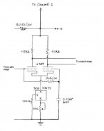
I'm confused by the output valves' cathode arrangement. Also, the bias isn't shown to be adjustable, except balance, and there's some confusion about which output valves are paired, etc. No doubt you intend to clean this up, but it's confusing.
ps: unless you have a distortion analyzer, there's no great need for the trimpot in the 6CG7's anode loads.
All good fortune,
Chris
ps: unless you have a distortion analyzer, there's no great need for the trimpot in the 6CG7's anode loads.
All good fortune,
Chris
Hi yes it’s confusing. I drew it the same as the original print that I had found for now. How it is, is the two inner tubes share a bias resistor/cap, the two outer share the same as well. I plan during the rebuilt to hide each power tube it’s own bias resistor and cap. I believe I would half the resistor value when going to individual bias resistors, correct? I have the bias resistors on terminal strips if I needed to change the bias.
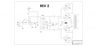
For now, I’m trying to get the new 6299 driver stage and 6CG7 LTP straightened out. Can anyone comment on if there are any obvious errors in those stages? Particularly with the CCS and negative supply wiring/voltages. I already plan to direct couple the 6299 to the phase inverter, I just need to reflect in the print.
Thank you
Individual cathode resistors would be twice as many Ohms. This is a good spot for surprisingly big capacitors; 470uF or twice that are not extreme at all. 100 Volt rating is fine. And, with cathode bias, you don't want or need an extra negative voltage to the grids.
All good fortune,
Chris
All good fortune,
Chris
Here's how I wired one in a recent build. (see attached). Not shown:
- The 10M45 is on a heat sink.
- There's about 8 mA going through the CCS
- The cathodes sit at about 100V
- Filament circuit for the 6FQ7 is biased up somewhat.
Where is your bias supply schematic? I didn't see it in your last schematic update.
- The 10M45 is on a heat sink.
- There's about 8 mA going through the CCS
- The cathodes sit at about 100V
- Filament circuit for the 6FQ7 is biased up somewhat.
Where is your bias supply schematic? I didn't see it in your last schematic update.
Attachments
Last edited:
Thank you,
I have updated the schematic to what I believe is correct. I kept Cathode bias since that is what I'm using now. I can switch to fixed bias if it is superior. Any thoughts? I have also changed the schematic to individual bias resistors and much larger caps.
I have also changed the CCS wiring to what is shown in the post #26 example.
Thanks again
Attachments
I prefer fixed bias in almost every case. If you go fixed bias you can add a bias and DC balance mechanism within the same circuit. I can show you a schematic snippet of how to do this if you're interested.
If you are wanting to keep it cathode biased, there is no benefit to individual cathode resistors. Use one cathode resistor for all four tubes
If you are wanting to keep it cathode biased, there is no benefit to individual cathode resistors. Use one cathode resistor for all four tubes
Last edited:
Here's the circuit I use for fixed bias. No balance pot is needed because they each get their own bias control.
Sharing a cathode resistor requires decent matching of the tubes otherwise you get current hogging. I suggest you use one resistor and bypass cap for EACH cathode. If not, don't be surprised to see one of the tubes red plating.
Sharing a cathode resistor requires decent matching of the tubes otherwise you get current hogging. I suggest you use one resistor and bypass cap for EACH cathode. If not, don't be surprised to see one of the tubes red plating.
Attachments
Sharing a cathode resistor requires decent matching of the tubes otherwise you get current hogging. I suggest you use one resistor and bypass cap for EACH cathode. If not, don't be surprised to see one of the tubes red plating.
Strongly seconded.
Chris
If you go with fixed (but adjustable) bias, you can add a small current sensing resistor between each cathode and ground (say 10 ohms). In a fixed bias arrangement, using separate bias adjustments per tube lets you bias each tube to a specific value that is easily measurable by measuring the voltage across each of the current sensing resistors.
If you use unmatched tubes current hogging is certainly a concern without separate bias adjustments or separate cathode resistors in a parallel PP topology. Tubes that were once matched can become unmatched over time. It does take up more space for the separate bypass caps though.
You will get slightly better measured performance if you use matched tubes regardless of the bias mechanism selected (but maybe it's not a concern to you in this build because you may not be able to hear the difference anyway).
Last edited:
Thanks a lot guys. After doing some more reading myself I think I want to change over to fixed bias while I’m making the driver and phase splitter changes.
Per Koda’s diagram in post #31, I should be able to fit these components no problem in the chassis. It might be a little challenge to fit another transformer in there for it though.
I should be able to get the power supply schematic done this weekend with the bias supply, then I’ll post it and see what you guys think.
Kward, you mentioned being able to post a bias supply example a couple posts back. Would you be able to post that so I may be able to reference that as well?
Thanks
Last edited:
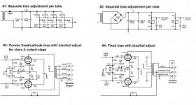
Here are some of the recent bias schemes for output stages I've done. Feel free to use these as you see fit and/or file them for future reference. For each case, look at the overall concept rather than at specific resistor/pot sizes and voltages. You will need to adjust resistor/pot sizes and secondary voltages used for each specific application given output stage needs and voltage swings needed.
The schemes shown in methods #3 and #4 are the bias/balance methods I was referring to earlier. These methods use the same number of pots as the individual bias approaches in methods #1 and #2, but can offer an advantage depending on your point of view. That advantage being that once you set DC balance, you are easily able to adjust bias up or down without upsetting balance, thus allowing one simple control to position bias where it works best for that particular output stage. On the other hand if you know exactly where you want to set bias and don't plan on changing it very often, the bias/balance method offers no apparent advantage over the separate bias adjustment approach. Overall though, I'd say there is not one "better" solution than the others--it just depends on what you prefer and the type of output stage you're dealing with.
Method #3 is a combination fixed and cathode bias. It uses the cathode voltage itself to generate a voltage that is applied to the grids. It is suitable for class A output stages.
Additional notes:
- For your amp, you can duplicate method #4 for each pair of output tubes in the push pull configuration. But again, whether or not this method is better or easier than the separate bias adjustment approach is up to you.
- In methods #2, #3, and #4, the system is setup so that if the wipers of the adjustment pots do ever disconnect from their track due to dirt, age, a defective pot, or whatever, the bias voltage does not become undefined. Rather, in that error condition, it forces the tube(s) into an overbias situation so they don't run away.
- For method #1, since it does not offer protection from a faulty wiper connection, I used sealed pots so that there is lesser chance of the pot wiper disconnecting over the lifetime of the amp.
- When designing a bias network for your output stage, it is important to offer the proper adjust range to account for mismatched tubes, but not too much adjust range so that a careless adjustment would cause red plating. I usually build in about 15% adjust range on either side of the nominal bias voltage desired.
- In a fixed bias output stage, it is also important to design the bias network so that it always comes up to voltage well before the output stage starts to conduct (from a cold start). That way the tube is never put into a runaway condition. This should be accounted for in the design phase of the amp.
Attachments
Last edited:
Thanks Kward for the thorough explanation.
I'm leaning toward #2 for simplicity and safety. I believe I would just add four individual channels, one per tube, correct?
I'm going to try to figure out voltages and component values and update my schematic. Tube datasheets are confusing to me.
Thanks
I'm leaning toward #2 for simplicity and safety. I believe I would just add four individual channels, one per tube, correct?
I'm going to try to figure out voltages and component values and update my schematic. Tube datasheets are confusing to me.
Thanks
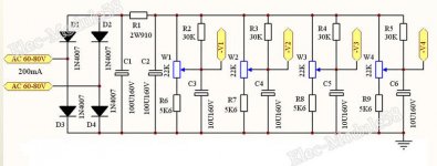
If you're feeling lazy, you can use one of these. I've used them and they work well enough.
Electron Tube Amp Negative Grid Bias Power Supply Adjustable 4channel for PP SE | eBay
Electron Tube Amp Negative Grid Bias Power Supply Adjustable 4channel for PP SE | eBay
Note in method #2, as shown on my previous post, a 2W pot was used. That's one of the negatives of that approach--bigger pots might be required since it changes current per leg based on pot setting. So to get the adjust range sometimes needed you need to start with more current flow, which then means a physically bigger pot that can dissipate more heat. I'm sure you could design it to use a smaller pot....but more work..") .
.
In method #1, I usually use 10 turn trimmer pots and mount (glue) them directly to the inside of the chassis with adjust nut facing up through the top of the chassis so if using a flat blade jeweler screwdriver, you can adjust bias without flipping the amp over or without removing a cover plate.
Anyway, good luck with yours!
.In method #1, I usually use 10 turn trimmer pots and mount (glue) them directly to the inside of the chassis with adjust nut facing up through the top of the chassis so if using a flat blade jeweler screwdriver, you can adjust bias without flipping the amp over or without removing a cover plate.
Anyway, good luck with yours!
Thanks Kward,
Since I have no experience in choosing a fixed bias circuit, I have no problem trying any of them. I’ll try number #1 then, I see why it doesn’t offer wiper protection as you mentioned, but I believe this is similar to the design Koda posted in post#31. Wouldn’t that scheme offer protection via the 30k resistors, or am I reading that wrong?
Since I have no experience in choosing a fixed bias circuit, I have no problem trying any of them. I’ll try number #1 then, I see why it doesn’t offer wiper protection as you mentioned, but I believe this is similar to the design Koda posted in post#31. Wouldn’t that scheme offer protection via the 30k resistors, or am I reading that wrong?
- Status
- This old topic is closed. If you want to reopen this topic, contact a moderator using the "Report Post" button.
- Home
- Amplifiers
- Tubes / Valves
- Monoblock redesign help