Hello all,
About 8 or so years ago I built a pair of monoblocks as my first tube projects and have been playing around with tube gear off and on since then. I’m still a newbie as far as designing my own circuits but not a newbie following a schematic or making some modifications to existing designs.
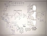
Back then I’ve settled on the attached schematic for some reason as my first project not knowing too much about what to look for, for a proper hi-fi amp.
I since then realize that this is more of a guitar circuit.
Since then, over this past summer, I re-chassied them and modified the circuit for greatly improved sound with the help of you guys. The schematic attached includes the modifications.
They actually sound pretty good I think but I’m sure they could be improved.
What I’m looking to do is further modify the circuit or better yet make a newly designed circuit more suitable for hi-fi. I would however like to retain the chassis, power tubes and all 3 transformers. I’m not opposed to ditching the choke if need be. I also have no problem swapping out the Ef86 or phase inverter. This goes without saying that I have no problem making a new circuit board and buying all new components except for the aforementioned.
Would anyone be able to point me in the right direction to a suitable circuit while retaining the power tubes and transformers? Or collaborate to help me design a suitable circuit around these components?
I’m currently using these to drive Elac F6.2’s for now but definitely want to upgrade them down the road.
Thank you!
About 8 or so years ago I built a pair of monoblocks as my first tube projects and have been playing around with tube gear off and on since then. I’m still a newbie as far as designing my own circuits but not a newbie following a schematic or making some modifications to existing designs.
Back then I’ve settled on the attached schematic for some reason as my first project not knowing too much about what to look for, for a proper hi-fi amp.
I since then realize that this is more of a guitar circuit.
Since then, over this past summer, I re-chassied them and modified the circuit for greatly improved sound with the help of you guys. The schematic attached includes the modifications.
They actually sound pretty good I think but I’m sure they could be improved.
What I’m looking to do is further modify the circuit or better yet make a newly designed circuit more suitable for hi-fi. I would however like to retain the chassis, power tubes and all 3 transformers. I’m not opposed to ditching the choke if need be. I also have no problem swapping out the Ef86 or phase inverter. This goes without saying that I have no problem making a new circuit board and buying all new components except for the aforementioned.
Would anyone be able to point me in the right direction to a suitable circuit while retaining the power tubes and transformers? Or collaborate to help me design a suitable circuit around these components?
I’m currently using these to drive Elac F6.2’s for now but definitely want to upgrade them down the road.
Thank you!
Attachments
a suitable circuit while retaining the power tubes and transformers?
I'd trade the input pentode for a real triode. The phase splitter could
then be a directly coupled differential amplifier, with the tail to ground.
But, do you really need so much gain (22k feedback resistor)?
Last edited:
Hi,
For starters, without the feedback loop added there was way too much gain and the amps were very noisy. I settled on 22k for the feedback resistors because it was as low as I could go without the amps oscillating. The triode wiring also helped tame some of the noise and improved the overall sound quality. Now the amps are very quiet.
I do like the current overall sound of the amps and they sound really great at low and mid listening levels and still sound nice at levels higher than I typically listen too. What I don’t like is that fact that I think they start to distort a little too soon when approaching higher volumes. Again, they are able to stay clean at volumes higher than I typically listen to but I’d like to see them be able to drive a little more.
I also don’t like the fact of how noisy they were without the feedback loop added and the triode wiring of the power tubes. I believe it was from excessive gain. From research, it sounds like a hi-fi amp should be very quiet with minimal feedback if any at all.
Let me know what you guys think.
Thanks again
A choke in the PSU filter is a good thing. Aside from ripple reduction, a choke helps with SS diode switching noise suppression.
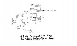
Mullard style circuitry mates well with so/so O/P "iron" quality and (IMO) so/so describes Hammond pretty well. A superior implementation of Mullard style topology is the Harman-Kardon Citation V. Notice the high gm theme in the small signal types. That high gm provides resistance to HF error correction signal induced slew limiting. The 12BY7 shown is getting scarce and (IMO) is best left for existing units. The 6922 cascode provided is a decent high gm substitute for the video pentode. The high gm theme can be carried further by using an ECC99, instead of a 6CG7, as the phase splitter.
An obvious improvement to long tailed pair (LTP), AKA differential, phase splitters is replacing the tail resistor with a constant current sink (CCS).
Attachments
Lots of good stuff already, but maybe a few other ideas:
The output stage seems the best of it, but a few changes for robustness and stability could be made easily. G1 stopping resistors at 10KOhms seem overlarge; maybe about 1KOhm. G2 should also have stoppers; 100 Ohms or so should do. Four separate cathode resistors with comparatively very large bypass capacitors (these tiny values come from an era when caps were expensive) give longer valve working life and lower transformer distortion (from lower idling DC offset).
Eli D.'s suggested drive circuit will be hard to beat. You really want quite a lot of current running through the driver valves. Type 5687 lets you run even more if desired.
All good fortune,
Chris
Hi guys, thanks for the input,
So i learn, what is the benefit of a high GM tube? Also, it was said the G1 stopping resistors of 10k are a little large and 1k might be better, how does this increase stability? And also note, that i do currently have 100R stoppers at G2.
So if the 6922 stage shown by Eli is the way to go I'll give it a shot. I just have a couple questions. I see it has a 425VDC regulated input, would an LR8K work for this? I noticed that this has a higher grid leak of 500K than i see on other designs I've looked at, usually around 100K, what is the benefit of this? Is the 1M pot a gain control.
As for the phase splitter, to go to a CCS, would that mean using something like an LT1085 wired as a CCS replacinf the 1.5K resistors off the cathodes? And is there another phase splitter design i should consider all together?
Once I decide on a circuit to try, I'll make a drawing and post it for review and markup.
Thanks for the help!
So if the 6922 stage shown by Eli is the way to go I'll give it a shot. I just have a couple questions. I see it has a 425VDC regulated input, would an LR8K work for this? I noticed that this has a higher grid leak of 500K than i see on other designs I've looked at, usually around 100K, what is the benefit of this? Is the 1M pot a gain control.
The cascode behaves much like a pentode. It is intended to drive a medium μ twin triode LTP phase splitter, not the paraphase splitter shown in the OP. Notice that the voltage amplifier is DC coupled to a LTP splitter, in Mullard style circuitry.
Cascodes and pentodes are not plagued by an adverse interaction between the grid to ground resistance and CMiller. That fact allows for a light load to be presented to the upstream circuitry. OTOH, triode CMiller combines with the grid to ground resistance to form an undesirable low pass pole. Hence the frequently seen 100 Kohm value.
It looks like a LR8 in each channel will work.
The 1 Megohm pot. sets the bias of the "upper" triode, which controls the current flowing in the entire assembly.
As for the phase splitter, to go to a CCS, would that mean using something like an LT1085 wired as a CCS replacinf the 1.5K resistors off the cathodes? And is there another phase splitter design i should consider all together?
A pair of IXCP10M45Ses would replace R10 & R31 in the Cit. 5 schematic. CCSes are not employed in the cathode circuitry of paraphase splitters. FWIW, paraphase splitters are currently out of favor.
OTOH, how'd you like to try something different? You already have a push-pull class A triode, pretty robust, output stage. There's just not much going wrong there. Distortion of most kinds is several orders of magnitude below any normal speaker. Frequency response is great with the triode's low source impedance to the OPT. Damping of the speaker's motor/generator is less than perfect, but can work great anyway.
So, with this really, really nice output stage as a given, what kind of driver would be ideal? The driver should take advantage of the amplifier's push-pull nature ASAP, read: immediately. This could be a differential input stage, then a direct-coupled push-pull cathode follower stage. No loop feedback. Maybe something like that, maybe something else, but always something that takes advantage of the differential nature of the amplifier.
No long loop feedback means no conventional instability. VHF parasitics come from "unconventional" instability - in the range where simpler, bulk value models no longer work (where a wire is no longer just a wire). Homebuilders can avoid parasitics just by following rules-of-thumb experience of the last century. Conventional instability caused by long loop feedback issues is less amenable to shade tree solutions.
Food for thought, or rambling, fine line, all good fortune,
Chris
Hi Chris,
I’m up to try just about anything as long as it retains the power tubes and transformers. I’m just looking to improve what I have which I don’t think will be hard to do when ditching the paraphase and the triode wired ef86.
My problem lies with designing these circuits myself, ie. Calculating values of components, voltages and currents needed for specific outcomes.
Would someone be able to explain or provide some links to what a differential input stage and a direct coupled push pull cathode follower is? Preliminary google searches left me more confused, perhaps they’re known be different names.
I’m assuming direct coupled means that it is not coupled to the next stage via coupling caps?
Thanks
The long-tailed pair 6CG7 stage in the previous schematic is an example of a differential amplifier. By making the common cathode resistor very large (compared to cathode input impedances) the anodes will have equal and opposite currents flowing through them. Ideally these days the common cathode resistor would be a couple-of-transistors constant current source. It's also has a push-pull amplifier's insensitivity to power supply noise and couplings.
Direct coupled just means that the driving anode is connected to the following grid without a capacitor, and so sets the grid's DC voltage at a fairly high voltage, just right for a cathode follower.
A nice layout might use a type 12AX7 input stage with constant current source to their cathodes, and a 6CG7 or 6SN7 or 5687 or even a 12AU7 push-pull cathode follower stage. Capacitors couple signal to the output stage grids, as already used, and you're done. No loop feedback is necessary, which is a great advantage for DIY. You'll need a small negative voltage supply for the CCS's, maybe -5 Volts at 5mA tops.
I'll try to get a streamlined schematic scanned in the next day or so, and posted. Successful amplifiers seem to rise or fall with the things often overlooked - grid stops, output Zobel networks, grounding, external ground loop mitigation, etc. - but a schematic is still better than a thousand words when the words don't have an iron-clad common meaning.
All good fortune,
Chris
Chris previously suggested no loop NFB. I appreciate his thinking that triode mode "finals" will have an adequate damping factor. However, a few dB. of GNFB will linearize the O/P trafo, especially at the frequency extremes, and (I repeat) Hammond stuff is so/so.
The nominal 6 Ω Elac speakers should be attached to the 4 Ω taps and their sensitivity derated for both that fact and the fact that 2.83 V. into 6 Ω is 1.3 W., not 1 W. If dynamically demanding material is to be played, ultra-linear (UL) mode "finals" could be a better option than triode mode.
The nominal 6 Ω Elac speakers should be attached to the 4 Ω taps and their sensitivity derated for both that fact and the fact that 2.83 V. into 6 Ω is 1.3 W., not 1 W. If dynamically demanding material is to be played, ultra-linear (UL) mode "finals" could be a better option than triode mode.
Thanks a lot guys for the help,
A schematic of the input and phase inverter you suggest would be very much appreciated especially since some circuits have multiple names and such.
You mentioned using a 12ax7 for the input, how would this compare gain wise to the EF86 I have now? The amp originally had way too much gain and was very noisy. Going to triode mode instead of a screen supply and especially adding GNFB quieted them down allowing them to sound pretty good.
If need be I can try both with and without GNFB and hear/ measure the differences.
The Elacs are currently connected to the 4R taps in which they sounded best. I am also not opposed to trying UL mode if need be.
Thanks again
Hello all,
Back in post #5 Eli posted a schematic of a Citation V and also a 6922 input stage as recommendations for an LTP phase splitter and Cascode input stage. This is to be integrated into my existing amps as an upgrade to the paraphase and EF86 I/P stage.
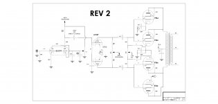
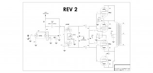
So I drew up a new schematic combining the 6922 Cascode schematic and taking the LTP from the Citation V. I did switch the 6922 to an ECC99 as was recommended.
On the new schematic I'm not exactly sure if all the component values and voltages which were taken from Eli's attached schematic would still hold true when mating to my output section.
I'm particularly confused with the LTP CCS wiring and the negative supply. I'm not sure if the negative supply would go to the CCS as I've seen on other LTP schematics or if it would go to the same place it would in the Citation V design, after the coupling caps. And is -54V correct/optimum?
I re-attached the existing amplifier schematic as well as the proposed "REV 2" schematic. Please feel free to mark it up with errors/ changes. Or let me know what to change.
Also note on the "REV 2" schematic, I haven't drawn the power supply yet but I will once the active circuitry is correct.
Thanks again for the help!!
Back in post #5 Eli posted a schematic of a Citation V and also a 6922 input stage as recommendations for an LTP phase splitter and Cascode input stage. This is to be integrated into my existing amps as an upgrade to the paraphase and EF86 I/P stage.
So I drew up a new schematic combining the 6922 Cascode schematic and taking the LTP from the Citation V. I did switch the 6922 to an ECC99 as was recommended.
On the new schematic I'm not exactly sure if all the component values and voltages which were taken from Eli's attached schematic would still hold true when mating to my output section.
I'm particularly confused with the LTP CCS wiring and the negative supply. I'm not sure if the negative supply would go to the CCS as I've seen on other LTP schematics or if it would go to the same place it would in the Citation V design, after the coupling caps. And is -54V correct/optimum?
I re-attached the existing amplifier schematic as well as the proposed "REV 2" schematic. Please feel free to mark it up with errors/ changes. Or let me know what to change.
Also note on the "REV 2" schematic, I haven't drawn the power supply yet but I will once the active circuitry is correct.
Thanks again for the help!!
Attachments

Last edited:
6CG7 LTP
Ok, I miss understood the use of the ECC99 then in the previous post. I’ll change the input stage back to 6299.
As far as the 6CG7 LTP, does the wiring and component values look correct?
Also does the negative supply enter in the correct place? And the CCS go to ground?
Ok, I miss understood the use of the ECC99 then in the previous post. I’ll change the input stage back to 6299.
As far as the 6CG7 LTP, does the wiring and component values look correct?
Also does the negative supply enter in the correct place? And the CCS go to ground?
Last edited:
Hello,
I edited the driver tube back to a 6299 as I had the wrong tube labeled there.
Would one of the experts be able to look over the driver and phase splitter stage? I'm especially confused with the CCS and the negative supply of the LTP. These were combined from schematics from post #5 and added to my existing output stage.
Any help would be greatly appreciated!
Attachments
- Status
- This old topic is closed. If you want to reopen this topic, contact a moderator using the "Report Post" button.
- Home
- Amplifiers
- Tubes / Valves
- Monoblock redesign help