Probability of wiper disconnecting with sealed 10 turn pots like Kodabmx showed on the bias board he linked to is near zero, in my opinion. You'll be fine. It's good to think about failure modes though. Sometimes they bite you when you least expect it.
Thanks for the help.
I’m attempting to figure the voltages and component values I need for my application but am having trouble finding where to start. I’m looking at the Tung-Sol KT66 datasheet and it states 100kohms max for fixed bias. That does this mean? Or how would I even do about calculating the circuit I need to make and the transformer requirements based off of the data sheet and my design? Very lost, lol.
Thanks
In method #1, I usually use 10 turn trimmer pots and mount (glue) them directly to the inside of the chassis with adjust nut facing up through the top of the chassis so if using a flat blade jeweler screwdriver, you can adjust bias without flipping the amp over or without removing a cover plate.
I use these. No glue required 🙂
10pcs WXD3-12 22K Ohm Multi-Turn Wirewound Potentiometer | eBay
Thanks for the help.
I’m attempting to figure the voltages and component values I need for my application but am having trouble finding where to start. I’m looking at the Tung-Sol KT66 datasheet and it states 100kohms max for fixed bias. That does this mean? Or how would I even do about calculating the circuit I need to make and the transformer requirements based off of the data sheet and my design? Very lost, lol.
Thanks
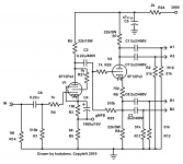
The values in the schematic I linked will work fine. You connect the bias voltage to the grid through the 100k or less resistor.
Thanks Koda,
Would the cathodes then connect to ground with say a 1R resistor to measure across? And would there need to be a bypass cap across the resistor? Or would the cathodes go directly to ground?
And lastly, since each tube will now have its own bias voltage coming from the bias supply, how do you isolate the two bias voltages per pair of tubes on either side of the OPT centertap since their grids are connected together from the phase inverter? All the examples I’ve seen only have two tubes.
Last edited:
I use 10R 2W on the cathode since it's easier to read (500mV instead of 50mV if using 50ma current).
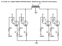
You will need to use a separate capacitor and resistor for each tube to isolate the bias voltages from each other.
You will need to use a separate capacitor and resistor for each tube to isolate the bias voltages from each other.
Here's the example from my PPP monobloc.
Attachments
Last edited:
Also, is it best to install a separate transformer for a bias supply if there is no bias tap on the transformer? Or is tapping off of the B+ an option?
I use a separate transformer or an isolated DC boost converter running from 12V... Some people have used voltage multipliers from the heater winding depending on the voltage needed.
This F-59X Triad Magnetics | Transformers | DigiKey should work nicely and it's cheap.
This F-59X Triad Magnetics | Transformers | DigiKey should work nicely and it's cheap.
I’ll probably go for the transformer because I have the room.
That voltages and cathode current would I be looking for, for triode wired Tung-Sol KT66’s? I was studying the data sheet earlier but was more confused than anything.
Thanks
That voltages and cathode current would I be looking for, for triode wired Tung-Sol KT66’s? I was studying the data sheet earlier but was more confused than anything.
Thanks
It should work fine... It'll make 80VDC. As I recall, running off 450 volts B+ made a 50V drop across the cathode resistor. 400V B+ fixed bias would require about -50V.
This is the best sheet I've found. The KT66 is electrically equal, but havdles higher plate dissipation.
http://www.tubezone.net/pdf/6l6g-stc.pdf
This is the best sheet I've found. The KT66 is electrically equal, but havdles higher plate dissipation.
http://www.tubezone.net/pdf/6l6g-stc.pdf
I'm not sure what voltages and outputs you're using, but:
According to Push Pull Calculator (from Glassware):
B+ 450V
Ik 50ma
Ra-a 4k3 (Hammond 1650N)
2 pairs of KT66 in push pull will need a bias of about -45V and make almost 25W in triode connection with a 15W class A limit. Third harmonic distortion is 1.1% without gNFB.
Pd is 22.5W/tube.
According to Push Pull Calculator (from Glassware):
B+ 450V
Ik 50ma
Ra-a 4k3 (Hammond 1650N)
2 pairs of KT66 in push pull will need a bias of about -45V and make almost 25W in triode connection with a 15W class A limit. Third harmonic distortion is 1.1% without gNFB.
Pd is 22.5W/tube.
- Status
- Not open for further replies.
- Home
- Amplifiers
- Tubes / Valves
- Monoblock redesign help