NuClassD circuit already has JFET buffers ahead of the NuTube. JFETs have a very high input impedance (1 meg?), in this case, limited to 100K by R3. Higher than 100K and you may start to pick up noise and/or RF.
10K pot would set the impedance the Allo Boss sees.
Thanks, this should work then. The Allo Boss itself can cope with loads down to 1kOhm.
Sorry but NuTube gain stage input impedance is lower than you think, even if buffered.NuClassD circuit already has JFET buffers ahead of the NuTube. JFETs have a very high input impedance (1 meg?), in this case, limited to 100K by R3. Higher than 100K and you may start to pick up noise and/or RF.
10K pot would set the impedance the Allo Boss sees.
R3 isn´t alone there, by any means.
It´s in parallel (for Audio that is) with R5 so that alone halves 100k.
But way more important, their junction is a node where NFB is injected , turning it into a virtual earth node, whose impedance by definition approaches zero.
You have to consider the value of R2 + RV2 (whatever it´s set to) divided by stage gain.
So the only resistor you can count on setting input impedance is R1
That said, yes, it will be easily driven by a 10k pot.
I'm just about to embark on a build of the NuClassD - have to say I'm rather excited. I plan to build an all in one unit incorporating a RasperryPi as streamer and a Soekris dam1021 as DAC.
I've hit a small snag, Mouser is showing the Ice Components 1D14A-100M as out of stock until October (!!!). I've fired off a few emails to supplies but I think I might be trying my luck.
Does anyone happen to have a source for these - I need 4 and I'm based in the U.K.
Or alternatively... can anyone recommend an alternative? Anyone that's build this amp before will know that space is tight - the footprint is 10.5mm x 15mm square.
Many thanks in advance.
...Ice Components 1D14A-100M as out of stock until October (!!!)....
On a glance:
Wurth Elektronik 7444011480100 is really 8mmX14mm on the board (16mm is high) and looks electrically appropriate. $4 but only 70 in stock tonight.
https://www.mouser.com/datasheet/2/445/7444011480100-1729674.pdf
Last edited:
Thank you for taking the time to search and reply! Do you think the lack of shielding would be a problem?
This one also seems like a close match - it’s shown as round on the data sheet but would fit the gap: 744750460100 Wurth Elektronik | Mouser United Kingdom
I must admit I don’t know too much about the role this inductor plays in the circuit but I’m guessing it makes up part of a filter?
This one also seems like a close match - it’s shown as round on the data sheet but would fit the gap: 744750460100 Wurth Elektronik | Mouser United Kingdom
I must admit I don’t know too much about the role this inductor plays in the circuit but I’m guessing it makes up part of a filter?
baseonmars:
The only one with that exact form factor that will fit the PCB directly and is also in stock (at least in the USA) is the 911-1D14A-330M which has a higher inductance rating. I would PM Pete Millet and ask his opinion. He has always been responsive to my queries.
BTW, NuClassD is well worth building. I did find the paralleled tube sections a bit harmonically rich. I set a few dB of NFB with the "gain" controls to avoid tube ringing, match channel gains and clean things up. Made a big difference.
And of course you can count on it contributing Johnson noise at the input too, much more than a 10k pot can. 47k is about 28nV/√Hz, far more than the low noise JFET that's been chosen to follow it...So the only resistor you can count on setting input impedance is R1
Regarding the inductors, Pete wrote back saying that they must be suitable for use in a Class D amp - the only alternative he knows of is the Sagami 7G14D-100 (7G14D-100M Sagami Elec | Inductors | Inductor Leaded - chip1stop.com).
Seeing as they're only available in Japan and shipping is expensive I've picked up two extra sets of 4. If anyone within Europe would like a set PM me - $20 + shipping.
Seeing as they're only available in Japan and shipping is expensive I've picked up two extra sets of 4. If anyone within Europe would like a set PM me - $20 + shipping.
Hi-
Several months ago I put together three of these boards for an amp (left, right and one for a 4-Ohm subwoofer with an off-the-shelf crossover). The power supply is a transformer from a Dynaco ST 120 through a new bridge rectifier, then about 10,000 uF of capacitors into a string of three linear voltage regulators which gets the voltage for the boards down to 29.5v. The audio input comes from a Millett NuTube headphone amp. The subwoofer input comes from the headphone amp's L and R tied together according to instructions in the oft-googled "Why Not Wye" article.
I have two problems:
First, a nasty thunk on shutdown coming from all three boards. I have checked the parts around the relay circuits and they all seem fine. A while ago I emailed Pete about this and he asked if I had enough capacitance on the power supply -- at the time I had about 4400. I increased this to the 10k mentioned and checked the parts he suggested, which all appear fine. Still, that shutdown thunk.
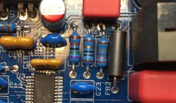
Problem two: the subwoofer board failed a couple of days ago. I hear a low-volume hum and thupthupthup sound with this board. I measured for DC on the output and got something unreasonable, around 700 millivolts. The other boards measure under 10. Using a non-contact signal tracer I hear the offending sound only around the parts seen in the attached pic. My guess is the MP7770 is toast. My hope is it's something else someone here will easily spot.
Thanks for any help.
Several months ago I put together three of these boards for an amp (left, right and one for a 4-Ohm subwoofer with an off-the-shelf crossover). The power supply is a transformer from a Dynaco ST 120 through a new bridge rectifier, then about 10,000 uF of capacitors into a string of three linear voltage regulators which gets the voltage for the boards down to 29.5v. The audio input comes from a Millett NuTube headphone amp. The subwoofer input comes from the headphone amp's L and R tied together according to instructions in the oft-googled "Why Not Wye" article.
I have two problems:
First, a nasty thunk on shutdown coming from all three boards. I have checked the parts around the relay circuits and they all seem fine. A while ago I emailed Pete about this and he asked if I had enough capacitance on the power supply -- at the time I had about 4400. I increased this to the 10k mentioned and checked the parts he suggested, which all appear fine. Still, that shutdown thunk.
Problem two: the subwoofer board failed a couple of days ago. I hear a low-volume hum and thupthupthup sound with this board. I measured for DC on the output and got something unreasonable, around 700 millivolts. The other boards measure under 10. Using a non-contact signal tracer I hear the offending sound only around the parts seen in the attached pic. My guess is the MP7770 is toast. My hope is it's something else someone here will easily spot.
Thanks for any help.
Attachments
Recommandations to reduce the voltage of the PSU?
Dear all,
I'm finalizing this amp and would like your advices/recommandations to lower the power supply voltage.
Living in France with around 240-243VAC measured out of the wall plug... The PSU is built around a toroidy 100VA 2x22V for 230V input. With 240VAC at its inputs it delivers around 24.5-25VAC which leads to near 33VDC at PSU output.
What would be the best way(s) to lower this voltage which I find too near from the limit of 35V mentioned by Pete on its website? As far as I understand (noob inside as you guessed), I can not use a regulator as it may be counter productive regarding the "shutdown detection" on the amplifier board. Some diodes to reduce the voltage? A voltage limiter? Change the transformer to something smaller?
Any recommandations or tracks I could follow would be greatly appreciated.
Thanks and take care!
Raph
"What would be the best way(s) to lower this voltage which I find too near from the limit of 35V mentioned by Pete on its website?"
I'm low on the knowledge scale here but if you're only trying to bleed off 4 or 5 volts a simple voltage divider would probably be fine. Do a web search for "voltage divider calculator" and you'll get plenty of results which will show how it's done and what values to use. The trick is to make sure the resistors are of adequate wattage. There are other calculators for that. Make sure the resistor wattages are double or triple of what the calculator indicates. The resistors will turn the extra voltage into heat.
I'm low on the knowledge scale here but if you're only trying to bleed off 4 or 5 volts a simple voltage divider would probably be fine. Do a web search for "voltage divider calculator" and you'll get plenty of results which will show how it's done and what values to use. The trick is to make sure the resistors are of adequate wattage. There are other calculators for that. Make sure the resistor wattages are double or triple of what the calculator indicates. The resistors will turn the extra voltage into heat.
Nothing to worry, difference is less than 10%your advices/recommandations to lower the power supply voltage.
Living in France with around 240-243VAC measured out of the wall plug... The PSU is built around a toroidy 100VA 2x22V for 230V input.
Actually 5.6% ;NOTHING to worry about.
That is absolutely UNLOADED voltage, it will drop with any sensible consumption.With 240VAC at its inputs it delivers around 24.5-25VAC which leads to near 33VDC at PSU output.
WHICH website?this voltage which I find too near from the limit of 35V mentioned by Pete on its website?
WHICH page?
WHAT does he say?
Are we suppossed to roam the Net to find data which you should have posted HERE?

In any case, you are UNDER his limit.
In principle, nothing is needed.As far as I understand (noob inside as you guessed), I can not use a regulator as it may be counter productive regarding the "shutdown detection" on the amplifier board. Some diodes to reduce the voltage? A voltage limiter? Change the transformer to something smaller?
Add useful data for a better answer.
WHICH website?
WHICH page?
WHAT does he say?
Are we suppossed to roam the Net to find data which you should have posted HERE?
Perhaps the site which is the topic of this thread, linked in Post #1 (now on previous page).
Reduce PSU output voltage
Hey,
let's go for a new episode of "the noob strikes back" (you should listen to the star wars theme when reading this
@jereid, thanks for your suggestion concerning the voltage divider. Although I did not mention it in the first place, I read here and there that it was not the good solution when current is higher than "low" and I'm not sure that it would suit the situation (as far as I can see there is around 80mA consumed by the amp without any signal input). JMFahey seems to confirm it would not be the right solution here, I may not follow this lead then.
You are abolutely right here, it's an unloaded PSU that I measured as I didn't want to take the risk to blow up anything. BTW, if I look at the schematic (and one more time, I AM A/THE NOOB here), it's not absolutely unloaded as there is 1K R between V+/V- just before the PSU output(?).
uh As we are on the NuClassD 50W hybrid amp topic, I refered to Pete's website. There is only one Pete with its source of truth
So, as others guessed, it's Pete Millet website linked in Post #1.
Here is what is written:
My Mom always told me to be careful and that's what I do
Any answer are welcome as I am the one willing for help. Yours was appreciated and I'll continue to dig around to find a solution to drop 4-5V as I'm not confident with being closed to the limits. I'll first do some measurements with the PSU loaded to see what happens
Thank you all.
Noob Skywalker.
Hey,
let's go for a new episode of "the noob strikes back" (you should listen to the star wars theme when reading this
@jereid, thanks for your suggestion concerning the voltage divider. Although I did not mention it in the first place, I read here and there that it was not the good solution when current is higher than "low" and I'm not sure that it would suit the situation (as far as I can see there is around 80mA consumed by the amp without any signal input). JMFahey seems to confirm it would not be the right solution here, I may not follow this lead then.
Nothing to worry, difference is less than 10%
Actually 5.6% ;NOTHING to worry about.
That is absolutely UNLOADED voltage, it will drop with any sensible consumption.
You are abolutely right here, it's an unloaded PSU that I measured as I didn't want to take the risk to blow up anything. BTW, if I look at the schematic (and one more time, I AM A/THE NOOB here), it's not absolutely unloaded as there is 1K R between V+/V- just before the PSU output(?).
WHICH website?
WHICH page?
WHAT does he say?
Are we suppossed to roam the Net to find data which you should have posted HERE?
uh
As we are on the NuClassD 50W hybrid amp topic, I refered to Pete's website. There is only one Pete with its source of truth So, as others guessed, it's Pete Millet website linked in Post #1.
Here is what is written:
pmillet external website see post #1 for references said:You want to keep the voltage as close to 28V as possible. <snip>
You will blow up the class D chip and maybe other stuff if the voltage gets over about 35V, so be careful.
My Mom always told me to be careful and that's what I do
Add useful data for a better answer.
Any answer are welcome as I am the one willing for help. Yours was appreciated and I'll continue to dig around to find a solution to drop 4-5V as I'm not confident with being closed to the limits. I'll first do some measurements with the PSU loaded to see what happens
Thank you all.
Noob Skywalker.
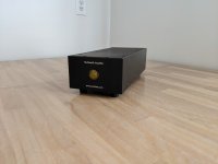
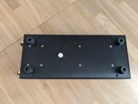
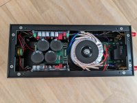
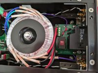
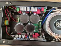
I built mine using the Landfall Systems chassis, like Pete did.
If you want to use the Landfall chassis, the power led, binding posts, and rca jacks are not listed in the bom. Here's what I used:
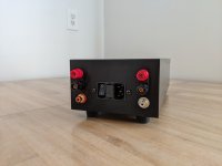
RCA Jacks:
NYS367-2 - red
NYS367-9 - white
Speaker binding posts:
Keystone 4109
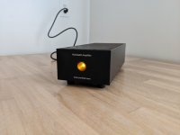
Front panel power light:
CNX722C400FVW (amber)
Pete uses CNX722C600FVW (blue) from the same series.
If you want to use the Landfall chassis, the power led, binding posts, and rca jacks are not listed in the bom. Here's what I used:
RCA Jacks:
NYS367-2 - red
NYS367-9 - white
Speaker binding posts:
Keystone 4109
Front panel power light:
CNX722C400FVW (amber)
Pete uses CNX722C600FVW (blue) from the same series.
Attachments
-
 PXL_20220617_113630759.jpg228.3 KB · Views: 63
 -
 PXL_20220617_113717236.jpg230.4 KB · Views: 53
 -
 PXL_20220617_113805780.jpg215.7 KB · Views: 60
 -
 PXL_20220617_113816171.jpg294.3 KB · Views: 66
 -
 PXL_20220617_113956166.jpg399.8 KB · Views: 67
 -
 PXL_20220617_114018883.jpg419.2 KB · Views: 67
 -
 PXL_20220617_114109299.jpg480 KB · Views: 62
Some tips that might be helpful to newbies:
RV1 - bias trim pot - before you fire up the amp up for the first time, give this pot about 10 turns clockwise. This will give you the lowest bias setting, and you can adjust up from there.
R4 - plate resistor - the bom specifies 100k here. Based on my experience and others here, you may need to increase this value (see posts #22 and #28). I ended up with 200k in mine. While you are putting in your Mouser order, you might as well grab a few values in between 100k and 200k. They are cheap enough. I would also recommend having R4 raised above the board a few millimeters to make removal a bit easier.
Setting the gain - I followed avdesignguru's method that he explained in post #34. This worked well for me.
This amp was a fun build. It sounds very good and it runs super cool. It will be my main summer amp.
Last edited:
- Home
- Amplifiers
- Tubes / Valves
- Posted "NuClassD" amp design: 50W hybrid class-D / Korg Nutube