Quick Question - C10 and C11.
On the PCB they are seperately 100uF/160vdc (C10) and 330uF/63v (C11).
In some of the BOMs they are shown as alternatives, with Mark preferring 330uF/100VDC
In the latest BOM they were shown as being diffewent for C10 and C11 again.
I'm fairly sure I can fit 330uF for both C10/C11, but just wanted to check here first.
I think I have managed to answer my own question. They key here is the bias supply, off the PSU. Since it will be over 100VDC (135V from the schema), then the electrolytic will need to rated in excess of that, and then there is the footprint on the board to consider, so then C10 ends up 100uF/160V.
6AV5 is a nice sounding tube in single ended, any one wants to try in a Baby Huey?http://www.r-type.org/pdfs/6av5ga.pdf
G2 can be fed from a regulated 150vdc supply...
The main thing of BH is being able to build a relatively cheap amp with the combination of UL and shunt feedback.
To apply UL with standard (so cheap) OPT you need g2 to resist high voltages and this doesn't. You may ask for a tertiary winding, but OPT price will double compared to standard ones.
To apply shunt feedback à la BH you need high gm and this hasn't.
I'm sure that tube is a very good tube for audio application, but maybe not for this specific kind of circuit. Maybe for the father of BH, Yves Monmagnon's amp with ECL86. Over there tubes are pentode connected so you can easily drop them wherever you want. But even there a bit more gm would be a plus there too.
Another question - C6 and C7 are 100uF 500VDC, 2 per channel. Since I am using the PSU, I have plenty of filtering from the 47uF + 470uF caps on that board. Do people fit C6 and C7 if they are using the PSU?
Also CX1 - is that meant to be X1 rated? I could not see that on the datasheet. Is it just bypassing the 100uF filter cap? If it not a bypass, what is its role?
Also CX1 - is that meant to be X1 rated? I could not see that on the datasheet. Is it just bypassing the 100uF filter cap? If it not a bypass, what is its role?
Another question - C6 and C7 are 100uF 500VDC, 2 per channel. Since I am using the PSU, I have plenty of filtering from the 47uF + 470uF caps on that board. Do people fit C6 and C7 if they are using the PSU?
Also CX1 - is that meant to be X1 rated? I could not see that on the datasheet. Is it just bypassing the 100uF filter cap? If it not a bypass, what is its role?
Found this reply from Marc regarding CX1 ....
CX1
For CX1 the value is not critical, it is just a HF decoupling and since I had plenty of 10 nF 1000 V in stock I use them, but a 100 nF 630 V can be used too
There is already C16 on the PSU board, 100nF 630V, so I think this is duplicating that component.
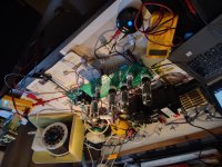
As is probably obvious, I am testing and getting close to first music ;-)
LM555 timer delay. I use the 33uF that is on the screen printing on the PSU board, and with the 2.2M resistor that gives 72s delay (actually 82s when I timed it). In the BOM it is stated as 10uF, and that would be a more reasonable 30 odd seconds. (Or is switching the resistor value the best strategy?)
Is there anyone compiling a list of deviations and errata so that a definitive v2.0 could be enshrined somewhere - maybe on the wiki? I have found it a bit of a struggle to reconcile the 1.4 and 1.5 versions, boards and BOMs.
Perhaps all the corrections and fine tuning could be gathered together and the definitive version dubbed the 'Baby Huey EL34 Marc', in his memory? I would be happy to subscribe to another set of boards.
OldHector,
Great suggestion to start a Wiki for a list of deviations, explanations and errata for a definitive BHEL34 V2.0. Since Marc did the Mk 2 version PCB and later the PS PCB they harbor a few (harmless) duplications as you have pointed out, but it certainly would help future builders is these things are sorted out and recorded.
You have been answering your own questions! I think you are doing a good job and agree with your answers .
.
Best wishes with your start-up and adjustment for good music.
Great suggestion to start a Wiki for a list of deviations, explanations and errata for a definitive BHEL34 V2.0. Since Marc did the Mk 2 version PCB and later the PS PCB they harbor a few (harmless) duplications as you have pointed out, but it certainly would help future builders is these things are sorted out and recorded.
You have been answering your own questions! I think you are doing a good job and agree with your answers
.Best wishes with your start-up and adjustment for good music.
The bleeder resistor for the 450uF cap on the PSU is 274K 2W. That means there will be 60V charge left in the electrolytic after approx 4 mins. I've used 2 x 150k 2W in parallel so that discharge time to 60V is 67s.
Bleeder calculator
Is there a more optimum value than 274K, or is it a personal choice? I'm quite nervous of these big caps ever since I picked up a guitar amp without fuses or tubes, or bottom plate. I saw one contributor here uses an LED as a visual reminder, and I am contemplating that.
Since there is a relay on the board, could a future enhancement be to have a DPDT relay, and for the discharge circuit to be triggered on power off?
Yes, that sounds reasonable. I had thought to use Marc's value when it is installed in a plinth, and parallel it whilst testing.
Music has not arrived yet. Lots of fun and games with the resistor values on the PSU board for setting the bias output. Found the relevant info in a post by gbowling (thanks! if you read this), and hope to have the right voltages when I try it out tomorrow. I also had fitted some 1meg resistors from a bag that was marked 10k, and originally thought that would be it.
I have 6 power supply boards, thinking I could use them as a generic supply for future projects, so a lot of fettling, solder sucking and tinkering.
Out of interest, does anyone use DC heating?
Marc and other folks used DC with a buck converter.
Others used AC and said that was fine too... so sounds like a personal choice.
I would only have concern with AC if the traces on the PCB were routed in a way that interfere with sensitive signals, but people used AC and said it works fine.
Keep in mind that with DC the heater tap on the transformer should be rated at 2X compared to AC.
I'll probably start off with AC and experiment with DC afterwards. My main reason for DC will be regulation, as my AC can vary between 118VAC and 123VAC depending on the time of day.
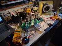
As Brian Wilson wrote, "I can hear music ... Sweet sweet music', and that was finally true today. I have Hammond 1650HA 6.6k output transformers, and it is the first build without toroids. First impressions were good, but maybe not quite the bass punch of the toroid. The EL34 tubes were biased low at 30ma, B+ 416V and I had no feedback, so expecting an improvement.
Now I need to make it presentable, which will keep me occupied for a while yet.
I am hoping I can finish it well enough to find a home for it, so I have an answer for the wife when she says "An amplifier? Why on earth do you need to build another one?" ;-/
Question: I have 416V from the 275VAC taps on the Toroidy PT - does anyone use the 330VAC taps and aim for 500V?
Attachments
Last edited:
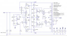
Hi, while playing with my cascoded version (njfet on bottom, 12ax7 on top) of this amp, I tried to simulate the circuit in attachment based on the BHEL34, but with a cascoded PI (12ax7 on bottom, SS on top).
This is the result with no global negative feedback, B+ 450V and 6k6 Raa at 40 Wrms:
Has anyone ever measured his BHEL34 to compare, or wants to check this solution on the boards?
R9 and R10 can be reduced in order to increase gain (at the expenses of less current lnfb) and apply some gnfb if needed.
R15 is there just to drop some negative voltage and improve the PI.
Vd are set to 130V for two reasons: it's the perfect reference voltage for the cascode and it's around 3 times the negative bias voltage (needed to properly supply the PowerDrive).
This is the result with no global negative feedback, B+ 450V and 6k6 Raa at 40 Wrms:
Code:
Harmonic	Frequency	 Fourier 	Normalized	 Phase  	Normalized
 Number 	  [Hz]   	Component	 Component	[degree]	Phase [deg]
    1   	1.000e+03	2.515e+01	1.000e+00	   -2.53°	    0.00°
    2   	2.000e+03	5.273e-03	2.097e-04	  -93.47°	  -90.94°
    3   	3.000e+03	1.906e-01	7.579e-03	   -7.61°	   -5.08°
    4   	4.000e+03	3.608e-04	1.434e-05	  -94.03°	  -91.50°
    5   	5.000e+03	2.490e-02	9.903e-04	 -163.85°	 -161.33°
    6   	6.000e+03	5.888e-05	2.341e-06	 -101.23°	  -98.70°
    7   	7.000e+03	8.209e-03	3.264e-04	   12.34°	   14.86°
    8   	8.000e+03	2.292e-05	9.112e-07	   26.88°	   29.41°
    9   	9.000e+03	2.154e-03	8.565e-05	 -165.04°	 -162.51°
Total Harmonic Distortion: 0.765391%(0.765398%)
Has anyone ever measured his BHEL34 to compare, or wants to check this solution on the boards?
R9 and R10 can be reduced in order to increase gain (at the expenses of less current lnfb) and apply some gnfb if needed.
R15 is there just to drop some negative voltage and improve the PI.
Vd are set to 130V for two reasons: it's the perfect reference voltage for the cascode and it's around 3 times the negative bias voltage (needed to properly supply the PowerDrive).
Attachments
Hi Roberto,
No hurry here, but it will appreciated when you get to it.
BTW, are you aware of the Toroidy transformers 33% Ul taps and 10% Cathode Feedback Windings? I hope their use might reduce distortion even further, a la Van der Veen.
The reason for my interest in these simulations is that I have a pair of these CFB transformers with Raa = 6.6k in storage that I would like to try in a BHEL34 sometime. Your modified circuit may be just right for it. See this one here:
TTG-CFB6600PP - Tube output CFB transformer [6,6kOhm] Cathode Feedback Push-pull - Shop Toroidy.pl
Best wishes with your audio and other pursuits this new year.
I wrote a very long post that the forum deleted. Great.
Francois, in attachment there's the schematic.
I've noticed the 3rd harmonic has an optimum when the current through the leds of the CCS of the PI is 6.8 mA vs 2 mA suggested by gingertube in the BH EL84 thread. Is it a simulation trick or it will be replicated in reality? Anyone knows?
I've seen those CFB transformers, but this cascoded driver is not enough for it.
Here I'm swinging 66Vpp to reach full power, but with 10% cathode feedback I'll need to swing 142Vpp that is 66Vpp plus 2 x 10% x (450 - 70)Vpp.
It is not possible to have the right gain nor the right THD from this cascode driver. I've reached 1%THD from a single triode of a 12AX7 using Rod Coleman's shunt cascode driver at 250Vpp without any feedback, but then it's needed to add a mosfet concertina or to add another complementary shunt driver. In that case you'll get very low THD, very high damping and again no gnfb.
I wrote to Rod to see if it was possible to have a pcb for this configuration: reading Bartola's test on it ( The Shunt Cascode Driver – Bartola(R) Valves ), it would be even possible to have no capacitors (except the ones on the power supply) on the signal path. A good thing for feedback loops.
Francois, in attachment there's the schematic.
I've noticed the 3rd harmonic has an optimum when the current through the leds of the CCS of the PI is 6.8 mA vs 2 mA suggested by gingertube in the BH EL84 thread. Is it a simulation trick or it will be replicated in reality? Anyone knows?
Code:
Harmonic	Frequency	 Fourier 	Normalized	 Phase  	Normalized
 Number 	  [Hz]   	Component	 Component	[degree]	Phase [deg]
    1   	1.000e+03	2.507e+01	1.000e+00	   -2.60°	    0.00°
    2   	2.000e+03	4.969e-03	1.982e-04	  -95.43°	  -92.84°
    3   	3.000e+03	1.597e-01	6.370e-03	   -8.25°	   -5.65°
    4   	4.000e+03	6.284e-04	2.506e-05	  -76.78°	  -74.18°
    5   	5.000e+03	3.172e-02	1.265e-03	 -162.04°	 -159.44°
    6   	6.000e+03	1.602e-04	6.390e-06	  118.35°	  120.95°
    7   	7.000e+03	9.332e-03	3.722e-04	   16.92°	   19.52°
    8   	8.000e+03	2.084e-04	8.313e-06	  -84.06°	  -81.46°
    9   	9.000e+03	2.917e-03	1.163e-04	 -165.57°	 -162.97°
Total Harmonic Distortion: 0.650902%(0.650943%)
I've seen those CFB transformers, but this cascoded driver is not enough for it.
Here I'm swinging 66Vpp to reach full power, but with 10% cathode feedback I'll need to swing 142Vpp that is 66Vpp plus 2 x 10% x (450 - 70)Vpp.
It is not possible to have the right gain nor the right THD from this cascode driver. I've reached 1%THD from a single triode of a 12AX7 using Rod Coleman's shunt cascode driver at 250Vpp without any feedback, but then it's needed to add a mosfet concertina or to add another complementary shunt driver. In that case you'll get very low THD, very high damping and again no gnfb.
I wrote to Rod to see if it was possible to have a pcb for this configuration: reading Bartola's test on it ( The Shunt Cascode Driver – Bartola(R) Valves ), it would be even possible to have no capacitors (except the ones on the power supply) on the signal path. A good thing for feedback loops.
Attachments
Roberto,
Thanks for providing the schematic and persisting after the forum deleted your attempt to post! This one is very informative.
Thank you also for your reminder about CFB transformers - I forgot about the additional drive requirements with them. I will have to learn LTSpice to play with and balance these things and devise a proper drive circuit for those Toroidy TTG-CFB6600PP transformers in the closet.
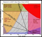
I don’t know if it is a simulation artifact, or some other cause, but I am dubious about the “optimal CCS current” result of >6 ma for two 12AX7 triodes. See the chart below.
Thanks for providing the schematic and persisting after the forum deleted your attempt to post! This one is very informative.
Thank you also for your reminder about CFB transformers - I forgot about the additional drive requirements with them. I will have to learn LTSpice to play with and balance these things and devise a proper drive circuit for those Toroidy TTG-CFB6600PP transformers in the closet.
I don’t know if it is a simulation artifact, or some other cause, but I am dubious about the “optimal CCS current” result of >6 ma for two 12AX7 triodes. See the chart below.
Attachments
- Home
- Amplifiers
- Tubes / Valves
- EL34 Baby Huey Amplifier