i all,
Can I build the el34 version but simply plug in 6550's? Do I need to change any components?
I have a pair of transcendar 80w 5k transformers in my parts box including a quad of new tungsol 6550's. But, in the future, I would like to be able to use el34's in the amp.
I'm a baby Huey veteran from a few years ago and still have my coke bottle 6v6 6sl7 amp. It was built with electra-print output transformers and sounds sublime. I'm hoping for something similar with the new build but with more power.
thanks in advance!
Andrew
Hi Andrew,
At which percentage are taken the UL taps in your 80W 5k OPT?
If you supply it at 420V B+, you can run both of them.
You need to set the bias to be able to have around -45V for the 6550 and -37 for the EL34, in order to get around 60 Wrms and 45 Wrms respectively.
Driver can be supplied with +40V and -110V circa to cover both options.
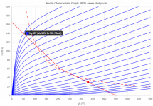
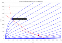
I have tried the BH circuit with:
- EL84 at 330V B+, 8k Raa and 23% UL;
- 6V6GT at 340V B+, 8k Raa and 23% UL;
- EL34 at 450V B+, 7k Raa and 40% UL, 7k Raa and pentode, 6.6k Raa and 23%UL;
- KT88 at 450V B+, 4k Raa and 23% UL;
My favourite is still the first.
At which percentage are taken the UL taps in your 80W 5k OPT?
If you supply it at 420V B+, you can run both of them.
You need to set the bias to be able to have around -45V for the 6550 and -37 for the EL34, in order to get around 60 Wrms and 45 Wrms respectively.
Driver can be supplied with +40V and -110V circa to cover both options.
I have tried the BH circuit with:
- EL84 at 330V B+, 8k Raa and 23% UL;
- 6V6GT at 340V B+, 8k Raa and 23% UL;
- EL34 at 450V B+, 7k Raa and 40% UL, 7k Raa and pentode, 6.6k Raa and 23%UL;
- KT88 at 450V B+, 4k Raa and 23% UL;
My favourite is still the first.
Last edited:
I have tried the BH circuit with:
- EL84 at 330V B+, 8k Raa and 23% UL;
…..
My favourite is still the first.
Interesting Roberto. Do you have thoughts on why this is the case?
Also, do you have any preference among these:
EL34 at 450V B+, 7k Raa and 40% UL, 7k Raa and pentode, 6.6k Raa and 23%UL. I believe, in theory, 43% UL is perfect for EL34 UL PP. Do you still believe that after your listening/measurements?
Interesting Roberto. Do you have thoughts on why this is the case?
The reason is IMO that EL84 (together with KT77 that I haven't tried yet with BH) is one of the tubes that get good linearity on the curves around their maximum anode dissipation whith low UL percentages (here below at 23%), and a smooth transition into distortion (also considering some AB2).
On top of that, a-g1 feedback helps to linearize more, and increase DF to better manage difficult speakers, whilst a can swing down to 50V when g1=0, giving almost 20 Wrms available.
Starting with 43% UL, anode reaches around 85V when g1=0, that means you won't exceed 15 Wrms. It could be that I have a music instrument background, but to me its' a synergic effect of different feedbacks. If you push too much one of the two, the result won't be optimal. 23% is what I've considered optimal in terms of available power plus internal resistance drop plus linearity. Then a-g1 makes the rest of the job.
No measurements, just listening after long simulations. It depends on the music and on the level you listen your music at (or better the power you require from it). I even liked it with 7k Raa in pentode (like the father of the BH) for easy music (few instruments) with 33k local feedback. 7k Raa and 40%UL sounds better with 15k local feedback for simple music and 33k for Rock. Same applies to 6k6 Raa and 23% UL. 39k is IMO too much, but it widely depends on the speakers and personal preferences too.Also, do you have any preference among these:
EL34 at 450V B+, 7k Raa and 40% UL, 7k Raa and pentode, 6.6k Raa and 23%UL. I believe, in theory, 43% UL is perfect for EL34 UL PP. Do you still believe that after your listening/measurements?
I will most probably write a suggestion for the PI's CCS current at different B+ voltages, because original schematic says 2.5 mA that is too much, and generally speaking other values seem quite high too. IMO it sounds better with less current. The point is to find the working point between the grid current (usually considered at 0,9V) and the current swing not to reach zero (depending on the a-g1 feedback resistor). Too much current, or too less, and you'll waste precious clean swing on the PI, limiting the available clean power of the amp.
Attachments
You are welcome Andrew,
with 40%UL power will be somehow lower, and won't differ that much from EL34 and 6550, you will hear more the "character" of the tube and the extended A class in this circuit rather than the power difference. I think that for tubes usually liking 40%UL, with this circuit 30% is enough and the a-g1 feedback covers the rest. Then of course there's the pentode configuration + a-g1 feedback path, that some like.
May I ask you how you set your 6V6 amp in terms of B+ and feedback?
I remember Ian suggesting 39k-18k-39k, 340V B+, 10k Raa with 40%UL on the full octal 6V6 amp.
Mine has 12AX7 as phase splitter, CCS set to have 670 uA per side, 47k-22k-47k (so same feedback ratio as Ian suggested, just 5V lower plate voltage for the 12AX7), +40 and -80V for the driver, 340V B+, 8k Raa with 23%UL. 100 Ohm on g1 and g2.
Hi zintolo,
It was 2013 when I finished my 6sl7 6v6 build. The opt's are electraprint 10k to yr with UL taps. It is easily the best sounding amp I've ever built or owned. I'll check the details tonight regarding b+ etc. From memory it puts out about 9 watts.
I've got a lot of 6v6's, most are used but test better than new on my avo 163. I've also got quite a few nos coke bottle types which is what I'm using.
I will update later on with more details.
Andrew
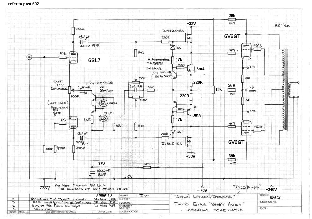
Here's the schematic I was working with for the 6sl7 6v6 BH. Note I used 39k 18k 39k.
View attachment 973208
View attachment 973208
Thank you Andrew!
Did anything go wrong with the attachment? It says it doesn't exist.
Is it following what is the latest update as per my knowledge?
EL84 Amp - Baby Huey
I've used a custom 8k with 23%UL instead of 10k with 40%UL because:
- I've it already for the EL84 version (main reason TBH);
- With 23%UL I can squeeze a bit more swing from the 6V6 (that are Russians 6P6S actually);
- With 8k I can reach a bit more of AB2;
- 12AX7 is almost mandatory because of the noval tube socket on the PCB.
Thank you very much!
Compared to yours I have:
Compared to yours I have:
- B+ at 340V vs 328;
- +40V (that is the expected +15V max on g1 plus 25V in order to keep the Ciss lower and stable) on driver vs +56V;
- -80V (that is expected -25V bias point, minus the expected 40V swing, minus a safety margin of 15V to always keep the driver operational) on driver and phase splitter's CCS vs -40V
- 12AX7 vs 6SL7;
- two red leds on phase splitter's CCS vs blue and green;
- 3,2 mA on driver's CCS vs 1,8 (that's 220 Ohm vs 390 Ohm);
- 100 Ohm grid stoppers on 6P6S vs 4k7 (Will the 6V6s work in AB2 with 4k7 in series from g1 to the driver?);
- 100 Ohm on g2 vs 150 Ohm (I've been told I could omit them as in old schematic, ans reply on output transformer winding resistance, but I preferred to overdo);
- 6P6S cathodes go to ground through 1 Ohm resistor each vs 10 Ohm each plus 10 Ohm shared;
- a-g1 feedback is 47k-22k-47k vs 39k-22k-39k, so same feedback for the output tubes, different working point for the phase splitter (that is normal, being another tube);
- OTP is 8k 23%UL vs 10k 40%UL (even if the schematic says 8k);
Hi,
just a consideration in case you want to use BH in class AB2:
The 12AX7 is supplied by the anodes of the output tubes. As the signal swings, in AB2 the plates of the 12AX7 go up, but the plates of the output tubes go down, so it reaches a point where output tubes' g1 cannot raise more.
I haven't reached that point in normal listening, but simulations showed the case.
I've searched the thread, but couldn't find a definite answer about selecting the value of R16 when there is a LED instead of R17.
I'm in the process of building the amplifier and PSU boards. It's my understanding that I should measure the -Vbias voltage at C10 and the select a suitable resistor for R16 according to this table:
B- [V] R17 R16
15 red led 5,8
20 red led 8,3
25 red led 10,8
30 red led 13,3
35 red led 15,8
40 red led 18,3
45 red led 20,8
50 red led 23,3
55 red led 25,8
60 red led 28,3
65 red led 30,8
70 red led 33,3
75 red led 35,8
80 red led 38,3
85 red led 40,8
90 red led 43,3
95 red led 45,8
100 red led 48,3
105 red led 50,8
110 red led 53,3
115 red led 55,8
120 red led 58,3
125 red led 60,8
130 red led 63,3
135 red led 65,8
140 red led 68,3
145 red led 70,8
150 red led 73,3
Is this correct? I'm assuming it's wrong to just measure the -Vbias voltage at the PSU board.
Then I wonder. Should I:
This is probably obvious to everyone else, but better to ask a question than doing something stupid ...
Trond
I'm in the process of building the amplifier and PSU boards. It's my understanding that I should measure the -Vbias voltage at C10 and the select a suitable resistor for R16 according to this table:
B- [V] R17 R16
15 red led 5,8
20 red led 8,3
25 red led 10,8
30 red led 13,3
35 red led 15,8
40 red led 18,3
45 red led 20,8
50 red led 23,3
55 red led 25,8
60 red led 28,3
65 red led 30,8
70 red led 33,3
75 red led 35,8
80 red led 38,3
85 red led 40,8
90 red led 43,3
95 red led 45,8
100 red led 48,3
105 red led 50,8
110 red led 53,3
115 red led 55,8
120 red led 58,3
125 red led 60,8
130 red led 63,3
135 red led 65,8
140 red led 68,3
145 red led 70,8
150 red led 73,3
Is this correct? I'm assuming it's wrong to just measure the -Vbias voltage at the PSU board.
Then I wonder. Should I:
- Guess a value for R16, solder it in, measure and then replace with correct resistor?
- Measure voltage without R16?
- Build the amp-boards with resistor in R17 and measure the voltage?
- Something else ...
This is probably obvious to everyone else, but better to ask a question than doing something stupid ...
Trond
Hi Trond,
put the closest commercial value to what you find on that table, it will be ok.
Thanks! I'll do that. But what I tried to ask is where do I measure B- voltage? Can I measure it on the PSU board (with or without a load). At C10 on the AMP board, perhaps without a R16 in place? I'm confused ...
- Home
- Amplifiers
- Tubes / Valves
- EL34 Baby Huey Amplifier