Thank you Francois,
I'm very slowly proceeding in designing the pcb for the hybrid cascoded BH, including the power supply on the pcb as in the first run of the BHEL34 (with bigger caps), and separate positive and negative supply of the powerdrive to easily allow different voltages (in module). This will allow to run big tubes even in AB2 with less than 1.5Vrms at its input.
I will post updates when available.
Question, Does a completely new version of this amp warrant a new thread? Seems like a "Hybrid Cascoded Baby Huey" thread might be appropriate. Especially since it's completely new boards, new schema, etc.
This thread is very long and difficult to navigate. If there are multiple versions included it gets really difficult to deal with.
Just a thought.
gabo
Back on possible mods I'd suggest, it's adding one more led in series with LED1 (refer to the schematic attached to the first post of this thread) between base and emitter of Q2 (PI's CCS bottom transistor).
This permits to have more control on the current of the CCS and so to tailor the working point of the phase inverter. This is something I suggest to work on to find its sweet spot (and avoid to have the 12AX7 working in a grid current zone).
This permits to have more control on the current of the CCS and so to tailor the working point of the phase inverter. This is something I suggest to work on to find its sweet spot (and avoid to have the 12AX7 working in a grid current zone).
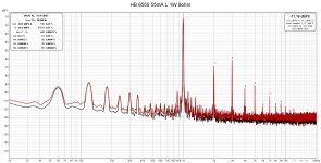
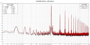
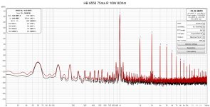
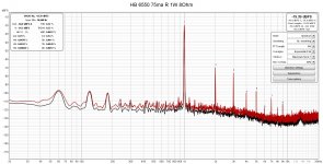
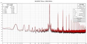
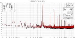
Some measurement of BH 6550 at 1W and 22W
Tube 6550 Winged C, 55mA Ia 425V B+. The gain is about x7.
the THD+N is large at 22W.
Also I noticed, if Ia increases to 65mA, it starts Oscillation.
Tube 6550 Winged C, 55mA Ia 425V B+. The gain is about x7.
the THD+N is large at 22W.
Also I noticed, if Ia increases to 65mA, it starts Oscillation.
Attachments
Last edited:
Hi wwwtttwww,
this is absolutely not normal, you should get that THD above twice that power.
Is it happening on both channels? Are TP3 and TP4 in the right range?
Also the 7x gain is quite low, you should have almost twice that.
this is absolutely not normal, you should get that THD above twice that power.
Is it happening on both channels? Are TP3 and TP4 in the right range?
Also the 7x gain is quite low, you should have almost twice that.
Last edited:
Tube 6550 Winged C, 55mA Ia 425V B+. The gain is about x7.
the THD+N is large at 22W.
Also I noticed, if Ia increases to 65mA, it starts Oscillation.
A couple of thoughts.
Driving 6550/KT88 to full power with a 12ax7 is an exercise in balancing the operating points and bias supply voltage to get the required clean voltage swing.
Have you checked the drive voltage going into the control grid of the output tubes. You could be getting clipping or soft limiting there.
Are you using global NFB? Gain of 7 is very low for no overall feedback.
Remove global feedback if using it and see if oscillations are still present. Also measure the power out etc. for comparison.
Are you using matched output tubes? One weak tube in a pair could be causing issues.
Bias supply voltage needs to be much higher than the -60 used for smaller tubes.
2.5 x the power tube grid bias would be a good estimate. So at -40v on the grid a bias supply of -100v is a rough estimate.
Hello Zintolo and Bfpca,
Thank you for your comments and hints.
I measured the gain with 0.1v, 1v and 2V 1khz input. They all same. Also I don't use global negative feedback.
For input valve, I use 5751, the gain is 70% of 12AX7. Is that the reason for low amp gain?
The output tubes are tightly matched quad, which I bought few years ago. On the box, Ip from 100.6mA to 103 mA and all Gm are 8400.
I tested a not well matched quad KT88, they have the same issue, Ia <65 mA, stable, >65mA, oscillation.
the B+ of small tube is in 233V, very balanced.
Do you have a fresh 12ax7 to try? If your gain is reduced to .7 in the driver that will cause lower overall gain. I’m puzzled by the instability without feedback. However, I don’t know how the local Schade feedback loop will respond to a lower gain tube as driver. Are your power supplies beefed up from the standard spec for the EL34? Also, what output transformer are you using?
Yes. I will try 12ax7.
The PW transformer has 400W. B+ has 320VAC and 400mA capacity.
In the test, when Ia increases to 75mA, the amp has the lowest THD+N, and sounds better than 55mA. With 8 ohms 50W resistor for measuring, there is no oscillation when Ia from 55mA to 75mA. But when speaker is connected, it starts to oscillate when Ia>65mA. The oscillation is audible like few khz.
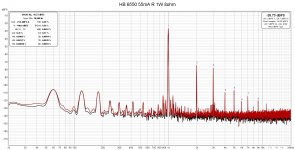
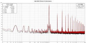
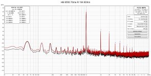
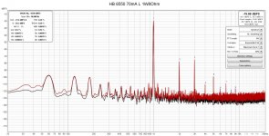
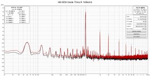
more measurements R channel
measured with resistor. no oscillation.
measured with resistor. no oscillation.
Attachments


Yes. I will try 12ax7.
The PW transformer has 400W. B+ has 320VAC and 400mA capacity.
In the test, when Ia increases to 75mA, the amp has the lowest THD+N, and sounds better than 55mA. With 8 ohms 50W resistor for measuring, there is no oscillation when Ia from 55mA to 75mA. But when speaker is connected, it starts to oscillate when Ia>65mA. The oscillation is audible like few khz.
When you connect a speaker it is a complex load impedance that will vary considerably in amplitude and phase. This makes most speakers more difficult to drive than their nominal impedance in resistance.
If your speaker is an 8 ohm load try using the 4 ohm output transformer tap and see if the results are the same.
I am not understanding the power transformer specs you mention above. 400w but only 320v at 400ma for B+. That looks like 128watts of AC available. If you look at your DC power for 4 tubes at 65ma and 425dc that works out to 102w of idle power. When the amp leaves class A that number will increase. Typically you want to have at least 1.5 and preferably 2 x the DC power available on the AC side. If your power supply is collapsing it could be causing the amp to oscillate.
When you say you can hear the oscillations, is that coming directly from the speaker or from the output transformer?
A couple of other questions.
Output transformers will sometimes ring audibly at certain frequencies on continuous tones.
What impedance and power rating are you running for an output transformer?
Have you double checked your bias setting calculations? What resistors are you using to measure voltage and calculate the current? I ask because once I built an amp and had poor results only to find that I had messed up the calculations and had 6ma of bias current instead of 60.
Hello Bfcap,
Sorry for misleading. 320VX400ma is the half of H+. So total is 2x320x400mA. It should be enough.
The sound is from speaker. When adjusting Ia (trimmer R41, R42), I can hear the frequency sweeping from speaker. Then it fades totally away when Ia<65mA.
For measuring Ia, I put two test points(Tp1 and Tp2) on R43(10ohms) and R44(10ohms) as in the original PCB.
I tried two sets of speakers. One 8 ohms and another one 6 ohms. I looked thru the forum. People are talking about a Zobel network on the secondary of the output transformer. The transformers(5k plate to plate, tapped 40% , 50W) I used may be not good enough. The last thing I would do is to buy some good output transformers.
I know it is very difficult to trouble-shoot without seeing, measuring and testing. Thank you very much.
Last edited:
No problem. Glad to help. If you have a 4 ohm tap you should still try your 8 or 6 ohm speaker on that tap to see how it behaves. It may be that the 4ohm tap is best for driving the speakers you have. Zoebel networks are not the answer. You should not be getting oscillations, particularly with no global feedback.
Looking at your power supplies, all of them, under load may reveal an issue that is causing the instability. Like you say, pretty much impossible to troubleshoot remotely. Finding out what is going on in a failure like this is always a good learning experience.
Brian
Looking at your power supplies, all of them, under load may reveal an issue that is causing the instability. Like you say, pretty much impossible to troubleshoot remotely. Finding out what is going on in a failure like this is always a good learning experience.
Brian
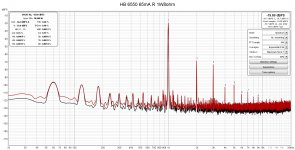
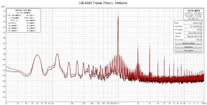
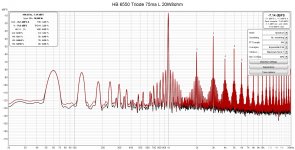
Baby Hue with 6550 triode mode
Changed the BH 6550 from Ultra linear to triode mode.
I found the triode mode has much better anti-oscillation capability.
All high frequency oscillation around 30khz-50khz is gone.
But something looks wrong with the left channel.
Changed the BH 6550 from Ultra linear to triode mode.
I found the triode mode has much better anti-oscillation capability.
All high frequency oscillation around 30khz-50khz is gone.
But something looks wrong with the left channel.
Attachments

Changed the BH 6550 from Ultra linear to triode mode.
I found the triode mode has much better anti-oscillation capability.
All high frequency oscillation around 30khz-50khz is gone.
But something looks wrong with the left channel.
that is called "funny business", did you try screen grid stoppers, say 470 ohms in ultra linear mode?
Hi wwwtttwww,
It seems to me that something is not correct, because you should get better distortion figures. Have you double checked everything? Would you report your voltages on different parts of the circuit to compare them with others?
It seems to me that something is not correct, because you should get better distortion figures. Have you double checked everything? Would you report your voltages on different parts of the circuit to compare them with others?
Hello Zintolo,
6550 B+ 425V, the voltage cross R43 and R44, 0.75V
Both 12AX7 B+ 208V,.
I looked thru the whole thread. Very few people posted THD+N pictures.
The number is little bit too high.
I am not too sure about the quality of my current OP transformers and ordered a pair edcor ones. But it may take months to come.
B+ at 425 V and 12AX7 at 208 V means 217 V across 267 kOhm so 0.813 mA each, so 12AX7 cathodes at around 1.8 V, that means you have around 0.9 Vp before grid current occurs, so (depending on the feedback you set) around 50 Vp of swing at 6550's g1.
I'd try to reduce the current through the 12AX7 at 0.7 or even 0.65 mA first.
Then I'd try also pentode configuration for the 6550s, trying screens at voltages between 250 and 300 to find the point where you like it most. A bit of gnfb could be needed together with local feedback.
I'd try to reduce the current through the 12AX7 at 0.7 or even 0.65 mA first.
Then I'd try also pentode configuration for the 6550s, trying screens at voltages between 250 and 300 to find the point where you like it most. A bit of gnfb could be needed together with local feedback.
- Home
- Amplifiers
- Tubes / Valves
- EL34 Baby Huey Amplifier