") & thanks I cant wait to get them built!
& thanks I cant wait to get them built! I was interested in the output of the voltage/splitter amp. I underderstand it fits within the envelope of the bias supply, but did not know how much.The maximum output will vary with power supply, tube type and output ....
...I'm not sure how well my KEF's will take to valves...
What KEF’s do you have? You may find a few clean tube watts sound better than losts of solid state watts.
Sowter OTs will definetely have good resale value it the UK; remember that OTs are like cars, they have a resale value. Toroidy may gain that resale value too.
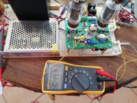
I have difficulty to have a stable 0 v dc between VC1 and VC2. The voltage varies between 30 mv to 450 mv. The voltage at C1 and C2 is only 114 to 115 v dc Look for assistance. Input B is 355v dc. Bias input is 55 v ac. I have set the Ia of the el34 at 50 ma.
Attachments
Last edited:
What KEF’s do you have? You may find a few clean tube watts sound better than losts of solid state watts.
Sowter OTs will definetely have good resale value it the UK; remember that OTs are like cars, they have a resale value. Toroidy may gain that resale value too.
I have a pair of Q35 floor standers (I'm looking for an excuse to build some).
Yes definitely and sometime increase! Potentially looking to build a winding machine to wind my own as I never have a big budget to work with.
Coincidences can sometimes surprise you. I just brought up the second channel of my BH last night and guess what, I had he same issue as you have. I traced it to the fact that I had not installed the 47.5 k input resistor to ground. Without a DC reference the tube won’t operate properly. Check the resistance from the grids of both input stage triodes to ground. I hope this solves your problem.
Check the resistance from the grids of both input stage triodes to ground. I hope this solves your problem.
Yes, this is exactly the same issue as mine..
I do have R6= 47K installed, following the schematic across Input 1 and input 2. After you findings above, i traced the pad and I discover Input 1 is not connected to R3. I need to jumper the pads.
Instead of jumpering, I wire up a 100K pot, and ignore R6. Now I can balance the voltage of Vc1 and Vc2
Thanks for all the help!
BUT, now V1 plate voltage of one board is 90V and the other is 120V (Both R18 is 680 Ohm- yes, I revert back following the schematic. I will install a trimmer in place of R18 and find a sweet spot. I assume Vc1 should be between 150~200
With a B+ of 343V, I should be looking at 1.16mA ~ 1.56mA total through R18
Great news that you found the issue. There are so many things that can happen to cause an imbalance like that. Yes, by all means experiment to find the proper current to get the plates where you want them. What I did was to install a higher resistor than needed and then paralleled resistors until I got the plate voltages where I wanted them.
Don't worry, less than 1 V is totally acceptable
For the plates, 115 V, it's a little bit low, I would recommend to increase R18 to 1k as suggested by Bfpca few posts ago, you should have about 150 V
Marc
I change R18 to 1K and the voltage at c1 and c2 measure 180 v dc.
The 300V ac input from the transformer drop to 275 on load.
Is this acceptable ?
it sounds pretty good playing through my test speakers .
The transformer is locally wound and I specified 300v ac output with 200 ma for mono side.
180V is good.
Higher triode idle current means more voltage drop across the 220K anode loads and so lower anode voltages.
The higher current also means higher grid current (grid current proportional to anode current).
Grid current (NEGATIVE Grid Current, that is current flowing out of the grid) develops a voltage across the grid leak resistors which subtracts from the bias. For good balance between the triodes you want:
- The grid leak resistances on the 2 triodes to be near equal
- The grid leak resistances to be relative low in resistance value (so the grid current does not develop significant bias voltage disturbances)
- Low grid current which infers low anode current
Cheers,
Ian

Good evening,
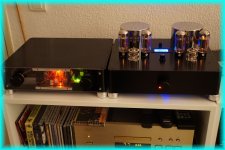
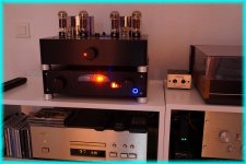
Here we go, this small group is now operational. It's a (long) but cool and informative project: Thanks Marc for his help for my novice mistakes ...
Cheers
Here we go, this small group is now operational. It's a (long) but cool and informative project:
Thanks Marc for his help for my novice mistakes ...Cheers
Attachments
Last edited:
Thank you Prasi.
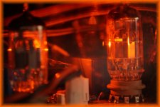
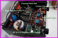
Here is another config for testing. It is easy to dress the front plexi. And also an internal view of the preamp with pré-amp line and RIAA mkII "Design by Marc". Like for the amp it's a mix MOSFET / tubes. They use ECC82 and also PC900 or PC97 for the pré-amp RIAA.
Music is beautiful.
Philippe
Here is another config for testing. It is easy to dress the front plexi. And also an internal view of the preamp with pré-amp line and RIAA mkII "Design by Marc".
Like for the amp it's a mix MOSFET / tubes. They use ECC82 and also PC900 or PC97 for the pré-amp RIAA.Music is beautiful.
Philippe
Attachments
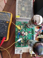
C1 measure only 20v and C1 measure 0.7 v dc
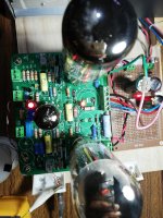
My second channel has a short from output 1 to ground and there is a burnt pcb at the site..
I cut the trace from anode of V2 and connect the output 1 directly from anode pin socket.
Manage to power up last and test for about 30 minutes.
On powering up again, the voltage at c2 onkt 0.7v dc and at c1 only about 20 v.
Tp1 and TP2 measure about 450mv
Please advice.
Attachments
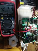
Noticed that the voltage across R10 measure 4v and 365V dc with reference to ground. I am going to replace R10 and R9 and check.
across R9 i measure 351v and 147 v.
Voltage across R18 measure 1.2 v.
i measure 348v at pin3 of V2 and V3.
Any other pats that i need to check and or replace ?
across R9 i measure 351v and 147 v.
Voltage across R18 measure 1.2 v.
i measure 348v at pin3 of V2 and V3.
Any other pats that i need to check and or replace ?
- Home
- Amplifiers
- Tubes / Valves
- EL34 Baby Huey Amplifier