For a voltage that low (150V Ebb) I would say an ECC82 won't work very well. That tube requires a bit higher voltage to work well as a buffer.
What would you think of using ECC88 instead? That's a common enough tube, and will work well with a 150V Ebb if you use a 15k cathode load resistor, 360 ohm cathode bias resistor.
Since ECC88 has a maximum heater-to-cathode voltage of only 50V, you'll need to reference the heater supply 'ground' to +75V or thereabouts. That's easy though. Just make a voltage divider of two 47k ohm resistors
Make the output capacitor a larger value, like 4.7uF, if you're going to use it into a contemporary amplifier like one of those little class D things. 1uF is fine if you're going to use it into a tube amp.
Something like this, maybe?
I agree on the usage of the ECC88 / 6922 / 6DJ8. A similar (though not identical) tube that will also work excellent here is the 6N1P.
Also, if you will only ever use it with amps that have a high input impedance you might get away with the 1uF cap, however, remember that there are a lot of really, really good amps that have an input impedance below 20K. As an example, the MC2 S800 has a 20K differential input. When driven single-ended, it will be about 10K. I'm the type of person who likes to try lots of different things, much of it professional equipment with 10K balanced inputs, so I built my preamp with a 4.7uF output cap.
Also, because the cap will have something like 80V of DC across it (if you're using 160V rails), turn-on transients are an issue. It's bad enough that it will make most professional amplifiers go into fault mode. You will need to come up with some sort of turn-on delay / muting circuit. This can be as simple as a relay with a transistor and an RC network, or something as fancy as a microcontroller.
Thank you for the replies. I don't have a ecc88 on hand
I have s stock of 4 ecc82 and i thought I could use it for good.so, i have to look for higher supplies may be a dc booster. But given the situation now, i can't get thinhs from China atleast for next few months. With disappointment,i have to postpone this project.
I have s stock of 4 ecc82 and i thought I could use it for good.so, i have to look for higher supplies may be a dc booster. But given the situation now, i can't get thinhs from China atleast for next few months. With disappointment,i have to postpone this project.
Doublers work great for preamps. 100 uF 200V caps are less than $1.50 at Digikey.
EEU-ED2D101 Panasonic Electronic Components | Capacitors | DigiKey
If you don't feel comfortable working with voltages in the 300V range, then you should still be able to get suitable tubes for use with a 150V supply, even without buying from China. ECC88, 6922, 6DJ8 and the 6N1P are all very similar. The 6N1P can be purchased from Russia, and you can also buy the 6922 / ECC88 / 6DJ8 from places like Antique Electronic Supply or Tube Depot. Since these are North American companies, shipping / import to India might be pricey (and I know a lot of people are experiencing financial uncertainty right now), but it is an option. As an alternative, I have had great luck with buying tubes on eBay, and you might be able to find a seller in your country since these are pretty common tubes.
Assuming you make the filter with decent vaules, you can use 22uF instead of 100uF anf use the money to get better caps like these 22uF 350V 12000 hour caps... 350V because they will effectively last forever when used conservatively... Even if you run them in a pot of boiling water, they'll last almost 2 years...
UCA2V220MHD Nichicon | Mouser Canada
UCA2V220MHD Nichicon | Mouser Canada
6N1P is not by any means "similar" to 6922/6DJ8.
6N23P is.
You are correct, they are not the same, and re-reading my last post seems to suggest that they are. They most certainly are not a "drop in" replacement for a 6922, but they are another option for this project. They actually work reasonably well in some circuits designed for the 6922, though usually not optimally. Their linearity tends to be pretty good, though since a CF has 100% feedback this isn't as big of an issue.
Also, when used in a doubler configuration (which would be my choice for this project), either cap option will realistically last several decades, so I wouldn't worry too much. In a doubler configuration 200V caps operate at about 75% of their rated voltage, so they should have quite a long life. The Panasonic caps linked are 10k hour 105C caps and are of high quality. Obviously you want to use decent engineering practice and avoid placing them right next to a power resistor that's dissipating a bunch of power.
The preamp I built a while back uses 820uF caps in the doubler, plus about 400 uF of capacitance after that. This is completely stupid an unnecessary for a preamp that only uses about 20mA for the two channels. All of the power supply components were bought surplus for essentially nothing, so the extra cost wasn't a factor.
As an interesting note on caps, the old MC650 amps (solid state) ran 88V rails on 100V 85C caps. Even among the ones that have run continuously since the late 90s (some on their third set of cooling fans), only a few have needed power supply caps replaced. If you use reasonable quality caps, and take a few precautions to not run right at the voltage rating, and avoid putting them on top of a blazing hot resistor, they tend to last pretty well.
Doublers work great for preamps.
Doublers work great, period. 2 of the very best power amps ever: the Harman-Kardon Citation II and Marantz 8B employ "full wave" voltage doubler B+ PSUs. As is the case for any rational topology, implementation details are crucial.
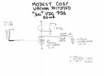
Doublers have been around longer than SS diodes. I'm providing a vacuum rectified doubler PSU that's suitable for use with preamps. The Triad N-68X isolation transformer it's designed around allows for world wide operation.
Attachments
Thankyou all. I have. 100 mfd 250 volt capacitors .so I understand that i can use them for doubler. Is a 470 ohm 1 watt resistor enough for the CRC? India is very much devoid of tubes. I can still get pcl82 near me, but not a single preamp tube. I just wiped the last 4 pieces of ecc82,( BEL , which was supposedly linked to mullard) .I am searching for projects,to put them into good use. My first thing is this preamp, second one is a 12 volt headphone amplifier. Two more tubes will ne stocked for spare use. As you rightly said, imports and financial struggles will be with us for sometime, and i have to use what is available locally. Electronics and audio is the only solace and time killing hobby for most people like us.")
Turning your bridge rectified 150V into 300V is as simple as swapping two diodes of the bridge with capacitors. Caps cost more than diodes, but still should be affordable, no? It's only a preamp, so 22uF/350V caps would be fine.
Do you need additional filter before the load?
I built a doubler, choke after the stacked capacitors, the another cap then 10k resistor into another cap, am getting horrible mains hum-
This is my first time to use voltage doubler-
Is it 50Hz or 100Hz? If 50Hz, it's not the power, and most likely a ground loop. If you have a DMM, measure the AC voltage on the B+ supply. Does the hum go away if you short the inputs?
If it's 100Hz, it's power related.
Usually, you build the doubler as if it was a diode bridge. Adding a large cap across the doubler caps might help if it's 100Hz.
If it's 100Hz, it's power related.
Usually, you build the doubler as if it was a diode bridge. Adding a large cap across the doubler caps might help if it's 100Hz.
Is it 50Hz or 100Hz? If 50Hz, it's not the power, and most likely a ground loop. If you have a DMM, measure the AC voltage on the B+ supply. Does the hum go away if you short the inputs?
If it's 100Hz, it's power related.
Usually, you build the doubler as if it was a diode bridge. Adding a large cap across the doubler caps might help if it's 100Hz.
Sometimes if it is 100 Hz (or 120 Hz in North America) the problem is still a grounding issue, and even if you add 10,000 uF of capacitance and a 20H choke it won't solve the problem. If you end up with 100 Hz noise on your signal ground (for example, charging pulses) you will end up with awful noise.
This is where an oscilloscope really does come in handy, since you can see exactly what the hum waveform looks like.
Edit: I also like to have at least one stage of RC filtering after the multiplier. It tends to quiet the power supply down quite a lot and for a preamp the additional cost is negligible unless you're going into production.
Interesting. I've never encountered a 100Hz problem that was related to grounding. Only the fundamental. Good to know.
I use many doublers, and never get enough hum through them to hear it on the output. I still suspect a signal ground loop issue.
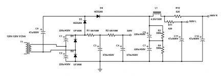
Here's an example of one of my supplies.
I use many doublers, and never get enough hum through them to hear it on the output. I still suspect a signal ground loop issue.
Here's an example of one of my supplies.
Attachments
Last edited:
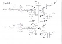
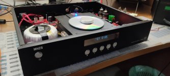
Mhzs CD 88 modding
Please i Need to calculating best resistors value for 12au7 tube instead 12ax7 original tube.
The tube out gain Is 1 , so i think is a buffer, i can also remove opamp, but in this case, i need tube stage with gain 2 , becouse opamp gain Is 2.
Please can you help me without change ht PSU value that Is 110v?
I have in my drawer also a couple of ecc88 if they are right for this pourpose.
Thanks
Attachments
Last edited:
You could try using this Universal loadline calculator for vacuum tubes - Vacuum Tube Amplifiers - DIY
or follow these steps - Load Line Calculations – wauwatosa tube factory
110V B+ is very low for tubes. Using a 12AU7 with that low of a B+ voltage, very low plate current and relatively high THD will be inevitable. What is the goal of this design? To add some audible 2nd harmonic distortion?
The gain from a 12AU7 will be in the neighborhood of 8x to 10x.
Do you need that much gain?
Last edited:
You could try using this Universal loadline calculator for vacuum tubes - Vacuum Tube Amplifiers - DIY
or follow these steps - Load Line Calculations – wauwatosa tube factory
I Need to know if resistors value are right , this Is the Electric diagram of my MHZS cd88 , originaly with 12ax7, now with 12au7.
110V B+ is very low for tubes. Using a 12AU7 with that low of a B+ voltage, very low plate current and relatively high THD will be inevitable. What is the goal of this design? To add some audible 2nd harmonic distortion?
The gain from a 12AU7 will be in the neighborhood of 8x to 10x.
Do you need that much gain?
- Home
- Amplifiers
- Tubes / Valves
- Tube Buffer Preamp Design