Matt,
You might also want to look at this info regarding the series limiting resistance requirement for the GZ34 if you haven't already.
The Valve Wizard
Just trying to be helpful.
Scott
You might also want to look at this info regarding the series limiting resistance requirement for the GZ34 if you haven't already.
The Valve Wizard
Just trying to be helpful.
Scott
Hi Scott,
Not sure if Antek are readily available over here or not. I've never heard of them, but then I'm hardly an expert so that probably doesn't mean a lot") .
.
I designed the circuit with Hammonds in mind, as thay have a good reputation and are available over here, at reasonable prices.
With hindsight, I'd have done more research into what was available before I started; I put a lot more effort into finding the right output transformer, I kind of assumed there'd be any number of mains transformers that'd fit the bill. Of course we all know where assuming gets you....
I'd probably go for Sowter, if money were no object, as they custom wind whatever you like at no extra cost. Perhaps they'll make a nice upgrade one day...
As an aside, how critical is having the capacitor before the choke, as well as after, in terms of performance?
Are we at the 'cork-sniffing' end of the spectrum, or is it a serious design flaw to omit it?
Matt.
Not sure if Antek are readily available over here or not. I've never heard of them, but then I'm hardly an expert so that probably doesn't mean a lot
. I designed the circuit with Hammonds in mind, as thay have a good reputation and are available over here, at reasonable prices.
With hindsight, I'd have done more research into what was available before I started; I put a lot more effort into finding the right output transformer, I kind of assumed there'd be any number of mains transformers that'd fit the bill. Of course we all know where assuming gets you...
.I'd probably go for Sowter, if money were no object, as they custom wind whatever you like at no extra cost. Perhaps they'll make a nice upgrade one day...
As an aside, how critical is having the capacitor before the choke, as well as after, in terms of performance?
Are we at the 'cork-sniffing' end of the spectrum, or is it a serious design flaw to omit it?
Matt.
I know I'm real late to the party, but IF I were doing this (and who knows… I just might), I like the simple enhancements that push toward higher linearity and more power. I might be a RightHandFool. LOL.
[1] paralleling output … easy. Use 2 EL84's in parallel. Small (100 Ω or so) anode drive-leveling resistors before the transformer. A 1.2 kΩ → 4, 8 Ω transformer.
[2] Leave stage 1 pentode. But… also… tame the gain.
[3] drop the cathode bypass on Stage 1. Tames the gain, significantly linearizes stage.
[4] add a DC blocking resistor to input. No point leaving a disaster-waiting-to-happen open. Good small-value caps aren't expensive. And contrary to a bunch of phools religiously held opinions, they're transparent. Just don't forget to use a pair of 1 MΩ resistors: one on each side of the cap, going to ground. Keep it relaxation discharged.
[5] add a stopper to each grid. Small values are OK: 1 kΩ or 4.7 khom. Oh, you could fairly easily do an analysis, but kilo-Ω lowness is goodness. Even sub-kΩ.
[6] regulate power supply legs. You show 300 and 320 V. Regulate the 300. Its easy, its nearly trivial, and it remarkably cleans up the PS. Bootstrapped is good.
[7] Fixed negative supply biasing of EL84. Essentially trivial. Increases power maybe 7%. Gets rid of the big cathode bypass cap. And the lossy resistor. A voltage quadrupler (semiconductor) gets the job done off the filament supply.
[8] binder post wiring. Old school. Practice good soldering technique. Check-and-recheck.
[9] use a nice box. A modular one - aluminum insides, wood outside.
[10] build as monoblocks. More duplication, but its also easier to keep track of what's what, and to eliminate cross-talk.
And that's about that! Everything has a purpose, none of it is hard, the results will definitely be superior, provided you use fine quality components. You're building a retro, steampunk, throwback-to-the-Pleistocene VALVE amplifier. Do it right.
Hopefully it doesn't fall on deaf ears. But if it does … that's OK too!!!
GoatGuy
I know I'm real late to the party...
...hopefully it doesn't fall on deaf ears. But if it does … that's OK too!!!
GoatGuy
Thanks for the input. At this late stage of the game, I'm afraid I've already settled on design decisions that render a lot of it redundant. If I followed even half of your suggestions I'd be starting again from scratch!
A lot of them also contravene the prime directive, to 'keep it cheap'. Real world budgets don't extend to parallel output valves or monoblocks (plus I'm using EL34s, not EL84s), although the parallel thing had crossed my mind - I tried something similar in a guitar amp a couple of years back.
Before I started this project, I made a promise to myself not to implement (too m)any concepts within the circuit without knowing why I'm using them. I'm sure all your suggestions are good ones (indeed, most of them are ideas I've come across on my travels), but I don't fully understand the reasoning, and especially the maths behind some of them. Until I do, I'll leave them alone. Better I think, to get something simple right, than to make a balls-up of something complicated
.Apologies for so comprehensively shooting your advice down in flames; I'll be sure to make use of what I can, to whit... points 8 and 9. Excellent advice. I've more or less got 8 covered, and 9 is already taken care of, although that's another story for another day.
Thanks,
Matt.
As an aside, how critical is having the capacitor before the choke, as well as after, in terms of performance?
Are we at the 'cork-sniffing' end of the spectrum, or is it a serious design flaw to omit it?
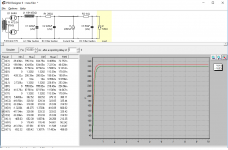
You can get reduced ripple using a capacitor input, but for that to be most effective as you have said your B+ goes way up using the transformer you have shown. Based on the PSUD2 simulation I did, with the choke input filter you have a pretty good spike at power on and about 500mV ripple on the B+. Someone please correct me if I'm wrong, but I think the ripple voltage is reduced at the output by the square of the output transformer turns ratio. If you are using a 5k:8, then 500mV/25 = 20mV ripple at the speaker. That is going to be fairly audible I believe.
Here is an interesting read about PSUD2 if you haven't seen it:
https://www.dhtrob.com/overige/pdf/dhtrob_psu.pdf
Scott
If you are using a 5k:8, then 500mV/25 = 20mV ripple at the speaker. That is going to be fairly audible I believe.
Here is an interesting read about PSUD2 if you haven't seen it:
https://www.dhtrob.com/overige/pdf/dhtrob_psu.pdf
Scott
Back to the drawing board then!
Unless I'm mistaken (and I frequently am
) there will have to be at least two more RC filters, to drop the voltage to 320V and 310V for the output valves and driver stage respectively. Can I expect these stages to aleviate the problem at all, or do I need to eliminate the ripple closer to it's source? edit:
I'm using a 2.5K:8ohm output transformer, not 5k;8ohm. Does that work in my favour, or against me?
Matt.
ps Thanks for the link. I'll have a read through that over breakfast tomorrow. Right now, the pub is beckoning...
Back to the drawing board then!
Unless I'm mistaken (and I frequently am
edit:
I'm using a 2.5K:8ohm output transformer, not 5k;8ohm. Does that work in my favour, or against me?
Matt.
ps Thanks for the link. I'll have a read through that over breakfast tomorrow. Right now, the pub is beckoning...
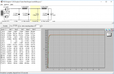
2.5k:8 would make it worse, however; I figured you were going to use an additional RC stage for the driver, but if you are going to use an additional RC for the output valves, that would get you much closer to what you want. Something like the attached.
Attachments
2.5k:8 would make it worse, however; I figured you were going to use an additional RC stage for the driver, but if you are going to use an additional RC for the output valves, that would get you much closer to what you want. Something like the attached.
Matt,
What current are you going to be running the EL34s at? For first RC after the choke, the 250R resistor would need to be a 25W part.
[1] paralleling output. easy. Use 2 EL84's in parallel. Small (100 Ω or so) anode drive-leveling resistors before the transformer. A 1.2 kΩ → 4, 8 Ω transformer.
[2] Leave stage 1 pentode. But. also. tame the gain.
[3] drop the cathode bypass on Stage 1. Tames the gain, significantly linearizes stage.
[4] add a DC blocking resistor to input. No point leaving a disaster-waiting-to-happen open. Good small-value caps aren't expensive. And contrary to a bunch of phools religiously held opinions, they're transparent. Just don't forget to use a pair of 1 MΩ resistors: one on each side of the cap, going to ground. Keep it relaxation discharged.
[5] add a stopper to each grid. Small values are OK: 1 kΩ or 4.7 khom. Oh, you could fairly easily do an analysis, but kilo-Ω lowness is goodness. Even sub-kΩ.
[6] regulate power supply legs. You show 300 and 320 V. Regulate the 300. Its easy, its nearly trivial, and it remarkably cleans up the PS. Bootstrapped is good.
[7] Fixed negative supply biasing of EL84. Essentially trivial. Increases power maybe 7%. Gets rid of the big cathode bypass cap. And the lossy resistor. A voltage quadrupler (semiconductor) gets the job done off the filament supply.
[8] binder post wiring. Old school. Practice good soldering technique. Check-and-recheck.
[9] use a nice box. A modular one - aluminum insides, wood outside.
[10] build as monoblocks. More duplication, but its also easier to keep track of what's what, and to eliminate cross-talk.
[1] you do not need that resistor if you stay with cathode (auto) bias
[2] for Pentode you then better to switch the output stage to UL, which cuses the higher Primary impedance OPT, typically at least doubled. You, actually, might like the result. Otherwise, the Pentode-Triode combination somewhat breaks the Triode-Triode natural distortion cancellation.
[3] or, use the LED bias, you might like it better.
[4] apparently, the capacitor is being ment, agreed.
[5] use grid-stoppers unless the amp's layout has been well-thought and the grid networks are reasonably short; in such case I never needed the grid-stoppers.
[6] absolutely. Even with silly TIP50 filter (instead of regulating) you get way cleaner B+.
[7] yes, but... the autobias is safer for the beginner in case if the B- is accidentally missing.
[9] agreed on aluminum, lately there are plenty of nice-&-complete looking ones on evil-Bay, no need for wood.
[10] as a less-hustle-alternative the Mains trafo with completely separated windings could be used just fine, e.g. the AnTek 1T230C fits perfctly
Now everyone wants their own EL34 Breed D
To sum it up, think of the amplifier like a pipe with water flowing from the neutral up the valves then down the capacitors, choke, rectifier and transformer.
Regulating a SET is weird, because the output transformer needs to swing as much voltage as possible, the regulator can lower the voltage if it raises and counter effect
Makes no difference where you smooth out the flow with components such as for big caps, big chokes. Smaller caps are used to reduce the 'ripples' near components
Matt,
What current are you going to be running the EL34s at? For first RC after the choke, the 250R resistor would need to be a 25W part.
Hi Scott,
Total current draw is 196.2mA, less 4.1mA for the driver. I've attached a more complete drawing of the power supply. Can't seem to get PSUD to export pretty pictures (or save for that matter!), so unfortunately most of the detail has been lost. These are the values I've plugged in:

I calculate the 220ohm resistor dissipates just shy of 14W, which is a lot. I've opted for a 20W part to be on the safe side.
Even so, I'm not really happy wasting that much energy. I'm thinking it might be in my best interests to think it through from the start. If I can't find a transformer to fit my voltage/current needs, perhaps I can adjust my voltage/current requirements to better fit available transformers.
Cheers,
Matt.
the 220 ohm is like a very small pipe which will stop any water flow changes.
The only thing that will enable surplus flow to collect is the 330uf capacitor, which means after a louder music section the amp will sound sluggish, limited by the 220ohm no matter how powerful the power transformer, it is going to heat up so much!
The only thing that will enable surplus flow to collect is the 330uf capacitor, which means after a louder music section the amp will sound sluggish, limited by the 220ohm no matter how powerful the power transformer, it is going to heat up so much!
...Can't seem to get PSUD to export pretty pictures (or save for that matter!)...
In Windows: PrtScrn and a graphics program to crop and annotate.
PSUD should be saving its own proprietary project files when commanded. I have several here. However when I attempt to Attach, DIYA forum objects "Invalid". ".PSU" is not on the list of approved file types. It maybe could be, at Admin's discretion. You can trick the upload by appending ".TXT", but it is not really a Text file so would confound many people. Running through a ZIP encoder may be the bestest/safest way to pass .PSU files through the forum.
Attachments
the 220 ohm is like a very small pipe which will stop any water flow changes.
The only thing that will enable surplus flow to collect is the 330uf capacitor, which means after a louder music section the amp will sound sluggish, limited by the 220ohm no matter how powerful the power transformer, it is going to heat up so much!
Indeed. The more I learn about power supply design, the more I realise I don't understand.
It's becoming increasingly apparent that this particular PSU is fundamentaly flawed; It seems a ground up rethink, of the entire circuit, is in order.
On the plus side, I've plenty of time over the holiday period to make the necessary changes. Aside from the related smoothing issues, dropping 72V across a single resistor can't be a good design choice. I fancy I could put those volts to better use powering the valves
.Matt.
In Windows: PrtScrn and a graphics program to crop and annotate.
PSUD should be saving its own proprietary project files when commanded. I have several here. However when I attempt to Attach, DIYA forum objects "Invalid". ".PSU" is not on the list of approved file types. It maybe could be, at Admin's discretion. You can trick the upload by appending ".TXT", but it is not really a Text file so would confound many people. Running through a ZIP encoder may be the bestest/safest way to pass .PSU files through the forum.
Thanks, I'll look into it.
Who'd have thought the PSU program would be more complicated than the power supplies it set out to design...
Matt.
Matt,
Yes, that's a lot of wattage to dissipate. That's why it's easier to start off with the desired xfmr voltage to start with and use the capacitor input before the choke to get the ripple down first. Then you don't need to drop the voltage and dissipate all that energy. It will work like you have it though. You do realize you can run the el34s at a higher voltage. No problem with 400v or so and 450v caps are standard availability. Motor run caps are also popular for higher voltages. Take the AC rating and x1.414 for DC rating. These usually come in 370 or 440 AC ratings.
When you have your psud2 graph displayed, use alt - prt screen, then paste to MS Paint and crop like PRR said. Save as png or jpg and your done.
Who'd have thought the PSU program would be more complicated than the power supplies it set out to design...;
I too think it odd that we need many seconds with a million transistors to estimate the response of a handful of simple parts over a part-second.
But the reactances are all exponential, and the rectifiers are nearly infinitely non-linear. There is no direct computational path. SPICE will trial/error many time-points until it converges near a result (or blows-up). PSUD seems to use a more heuristic approach, which is often very good, but extreme values will provoke wrong answers (inconsistent with each other and with hand-sketch).
The Export Image lack is because PSUD has been around a LONG time, before we were trading pictures through the innernet. It's not a big deal, because most practical problems can be described with a few values, then others can put those values in PSUD or other simulator.
It is, IMHO, VERY useful to know how to figure this stuff by hand. Remember there were no simulators for 50 years of electronics, and no sims in basic supply design for another 20 years (the chip-designers hogged the sim). If you must use hollow-state rectification, design curves are IN the better data-sheets. Note the difference between Choke input and Capacitor input!! Note that the factory plots assume some value of transformer impedance which will be different in your PT. Old curves assume old-size caps, like 20uFd, when 40uFd was a LOT. Today 400uFd is less than lunch. This can be used but only if the source impedance limits rectifier strain. This is double-hard to hand-figure, and where PSUD etc become very helpful.
[1] you do not need that resistor if you stay with cathode (auto) bias
[2] for Pentode you then better to switch the output stage to UL, which cuses the higher Primary impedance OPT, typically at least doubled. You, actually, might like the result. Otherwise, the Pentode-Triode combination somewhat breaks the Triode-Triode natural distortion cancellation.
[3] or, use the LED bias, you might like it better.
[4] apparently, the capacitor is being ment, agreed.
[5] use grid-stoppers unless the amp's layout has been well-thought and the grid networks are reasonably short; in such case I never needed the grid-stoppers.
[6] absolutely. Even with silly TIP50 filter (instead of regulating) you get way cleaner B+.
[7] yes, but... the autobias is safer for the beginner in case if the B- is accidentally missing.
[9] agreed on aluminum, lately there are plenty of nice-&-complete looking ones on evil-Bay, no need for wood.
[10] as a less-hustle-alternative the Mains trafo with completely separated windings could be used just fine, e.g. the AnTek 1T230C fits perfctly
Why Thank You for the detailed reply!
[1] Perhaps. I'm OK with-or-without, but the OP sez... "no parallel tubes"
[2] is answered with [3]
[3] uses local-negative-feedback (unbypassed cathode resistor) to drop gain and linearize transfer function. Works well. Cheap too. "just get rid of the capacitor".
[4] yep
[5] They're cheaper than dirt (in the philosopy of the OP), so "get em, and use 'em. There is NO downside. The upside is RF oscillation quenching.
[6] Yep.
[7] Yep, I guess so. This was the most "stretch" of my ideas.
[9] Aluminum that looks good? Who knew! (tongue-in-cheek). Cool!!!
[10] I like your idea. Is such a transformer cheap (enough)? OP is $ sensitive.
GoatGuy
the 220 Ω is like a very small pipe which will stop any water flow changes.
The only thing that will enable surplus flow to collect is the 330uf capacitor, which means after a louder music section the amp will sound sluggish, limited by the 220Ω no matter how powerful the power transformer, it is going to heat up so much!
Yep. It is for this reason that one doesn't "design to a voltage spec" for the finals. It is a common mistake - especially for people who like using "design tools" - without really knowing the math itself that makes their designs accidentally work on paper.
There's one thing to keep in mind: Up to "the final" stage, the lower stages use so little current, and so well averaged by RC filtering, that they can be done in exactly the CRCRC… fashion the OP imagined. The final tho? It seriously just needs to be transformer → rectifier → capacitor → smallish inductor → capacitor. If it HAPPENS to be "320 volts", well alright. If it is 343 or 361 or 299, also "alright". More is better, but only up the dissipation and design limit of the output tube. And luck.
Moreover, the output transformer - especially in a SE design - is itself quite a filter. it does a good job isolating any unfiltered-out power supply hum from the plate of the EL–34 (or whatever) final tube. Nature of inductors. Even if they include transformative secondaries!
I had written (and now erased) a longish comment about REGULATION. While it definitely behaves like a "smart resistor" (becoming low impedance when surges of current are needed), it also has its own complications. Better is to have 2 high-volt supplies. (Can be off the SAME secondary, by using separate bridge rectification).
One supply for the finals. One for all the prior stages. Real regulation of the pre-final supply. Nothing except T→BR→C(50–100 μF)→L(2–10 H)→C(250+ μF). No regulation.
As to the giant voltage swings expected in a SE, yes: its true. But by going this route (above), you get past the sluggish issues pretty handily. Nice amplifiers from optimum number of components.
--------
GoatGuy
PS: its also why in my original "10 point list", I advocated a –24 V supply for biasing the EL–34. Gets rid of a big power-wasting resistor as a cathode-bias device. But then, I don't mind "reasonable complexity" in an amp. As long as it is cheap, reliable, conceptually simple and doesn't require exotic components.
- Status
- This old topic is closed. If you want to reopen this topic, contact a moderator using the "Report Post" button.
- Home
- Amplifiers
- Tubes / Valves
- Designing a Single-Ended Triode EL34 Power Amp