I would suggest to copy one of the great SET designs, its simply stupid to invent the wheel a second time. In tube audio schematics, everything has been done a dozen times already. Nothing new under the sun if you prefer a classic design. Even SRPP or other special circuits have been done by the japanese since 40 years. The other great designs came from 50 years before or older. But EL34/EL84 was the great time of push-pull. So if you want SET you have to search for tubes like 6V6 or other old octals.
If you have the intention to build SET, you should know before why (because of a special kind of sound quality that is preferable). Otherwise you could build PP like all other people will do. In the end, a great PP design eats any badly designed SET for breakfast. Its fast and its furious. SET tends, in most cases, to be slow and blurry sounding. Most of them indeed sound so boring to my ears, I would not prefer them. And 99% of all amateur circuits on the net have great faults either in circuit design or in the dimension of component values. So better to copy a professional circuit.
If you have the intention to build SET, you should know before why (because of a special kind of sound quality that is preferable). Otherwise you could build PP like all other people will do. In the end, a great PP design eats any badly designed SET for breakfast. Its fast and its furious. SET tends, in most cases, to be slow and blurry sounding. Most of them indeed sound so boring to my ears, I would not prefer them. And 99% of all amateur circuits on the net have great faults either in circuit design or in the dimension of component values. So better to copy a professional circuit.
I understand where you're coming from. There are obviously hundreds of tried and tested designs out there, all of which will likely be better than my own design.
I've built a half dozen amps from kits and schematics already - this project represents an attempt to actualy learn how an amp works, rather than simply assembling one parrot fashion.
I'm perfectly clear in my own mind about what I want to do, and why I want to do it, I just need a little help with the how.
As you say, re-inventing the wheel is stupid, but it's my time/money to waste as I see fit, it certainly won't be the most stupid thing I've ever done 🙂.
Matt.
OK Matt, then here you go...
So why not taking one of the great Klangfilm designs and take it a step further? Theres often something to improve in the power supply section and some tube types to change and play around.
So why not taking one of the great Klangfilm designs and take it a step further? Theres often something to improve in the power supply section and some tube types to change and play around.
Last edited:
reinventing the wheel
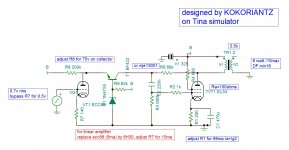
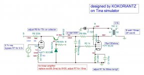
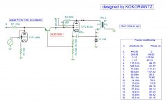
Extra power,higher DF,lower distortion from SE pentodes
try 3.3ohms (your design Ri) in series with your speakers and listen about an hour or two, than decide.
Extra power,higher DF,lower distortion from SE pentodes
try 3.3ohms (your design Ri) in series with your speakers and listen about an hour or two, than decide.
Attachments
Member
Joined 2009
Paid Member
I dont know if the OP is coming back after being bombarded by the whydoncha brigade but my suggestion is to build a test chasis. Get an Al chassis from Hammnd or equivalent and build your amp. Then test and play with the design, being very mindful of electrical safety. You can install extra parts, change things around, drill holes and cut outs all over the lace. Only when finished do you start with a new chassis, cut all the holes per the final design, paint it up and build it nice.
My first amp was build it right first time, only I rebuilt it twice and never tried out things that I should have, never learnd much. Later I got an experimental chassis from a friend who had finished with it and I started to play. I learned so much more and really enjoyed the process. I have found this by far the best way to learn and to develop a new design until I am happy with t. And its mre fun.
My first amp was build it right first time, only I rebuilt it twice and never tried out things that I should have, never learnd much. Later I got an experimental chassis from a friend who had finished with it and I started to play. I learned so much more and really enjoyed the process. I have found this by far the best way to learn and to develop a new design until I am happy with t. And its mre fun.
I dont know if the OP is coming back after being bombarded by the whydoncha brigade...
I had indeed ducked behind the couch, hoping they hadn't seen me. Have they gone now? 😉
...my suggestion is to build a test chasis. Get an Al chassis from Hammnd or equivalent and build your amp. Then test and play with the design, being very mindful of electrical safety. You can install extra parts, change things around, drill holes and cut outs all over the lace. Only when finished do you start with a new chassis, cut all the holes per the final design, paint it up and build it nice.
This is exactly what I plan to do (although I've a handful of old chassis knocking about, ripe for canibalisation - one expense spared!). Perhaps I should have made that clearer up front.
I've been messing around with electronics on and off most of my life (guitarist by nature, so I've mainly concerned myself with FX pedals and guitar amps, a bit of studio gear here and there).
The past two or three years I've finally knuckled down and tried to learn the theory behind the schematics, which has been a slow process but one I'm pleased I started. This amp will be by far the biggest challenge I've set myself, and - in spite of what some posters here assume - is a project I've given a lot of thought to.
I'm not setting my sights too high, in fact I'll settle - initially - for an amp which passes a signal from input to output without consuming any of it's constituent parts🙂. Should I pass that hurdle, I'm expecting a lot of further head-scratching, part swapping and general tinkering - with maybe just a little fun thrown in - before arriving at a product which approaches listenable. But we'll see, maybe I'll get lucky...
Matt.
If you like grid current at the input 😕listen about an hour or two, than decide.
Mona
Attachments
I dont know if the OP is coming back after being bombarded by the whydoncha brigade .
What are you doing differently than suggesting another possibility and mockering about other people???
I'm not setting my sights too high, in fact I'll settle - initially - for an amp which passes a signal from input to output without consuming any of it's constituent parts🙂.
Matt.
Everybody wants this but nobody has reached the goal.
What are you doing differently than suggesting another possibility and mockering about other people???
Take in stride Schmitz! Let the LeftHandFool build his amp, that's the best diy way.🙂
Getting closer...
Thanks to everyone for responding. With your help I have arrived at preliminary design which I'm confident is a workable starting point.
Next up, the power supply - I'll keep you posted...😉
Matt.
Thanks to everyone for responding. With your help I have arrived at preliminary design which I'm confident is a workable starting point.
Next up, the power supply - I'll keep you posted...😉
Matt.
Good evening all,
I haven't had much time lately to work on my project, so the power supply is still to do. I have had time to re-work the driver stage.
Following the advice given I've re-designed it around an ECC81, as opposed to the EF86 I was using earlier:

One triode drives each channel, saving on parts and space, which is a win/win situation 🙂.
Any thoughts? I'm aware that this is just about as simple as you can get, but I'm trying to keep things that way for the time being, until I understand a little more about valve theory, and indeed electronics in general.
I've calculated the R out of the ECC81 as 10K, which is on the high side. Will this load the output valve too much? If so are there any simple fixes?
Thanks,
Matt.
I haven't had much time lately to work on my project, so the power supply is still to do. I have had time to re-work the driver stage.
Following the advice given I've re-designed it around an ECC81, as opposed to the EF86 I was using earlier:
One triode drives each channel, saving on parts and space, which is a win/win situation 🙂.
Any thoughts? I'm aware that this is just about as simple as you can get, but I'm trying to keep things that way for the time being, until I understand a little more about valve theory, and indeed electronics in general.
I've calculated the R out of the ECC81 as 10K, which is on the high side. Will this load the output valve too much? If so are there any simple fixes?
Thanks,
Matt.
Your 12AT7 operating point pencils out, but the cathode resistor doesn't need to be a 5W part (it dissipates less than 0.01W).
The 12AT7 operating point doesn't take advantage of the generous plate dissipation available with that tube, but I'd say build it as-is first, then you can mess around with changes later. With your available voltage, loading the 12AT7 with a plate choke or CCS might be a good idea down the road.
The 12AT7 operating point doesn't take advantage of the generous plate dissipation available with that tube, but I'd say build it as-is first, then you can mess around with changes later. With your available voltage, loading the 12AT7 with a plate choke or CCS might be a good idea down the road.
I would consider adding a small (ie 47 ohms) placeholder resistor in between the 470R+330uF to ground. This way, later on if you want/need, you can adjust the audio out come by adding NFB without rearranging all your pretty layout and wiring. I would also add a grid stopper resistor (ie: 10K) to the grid of the EL34 for the same reason.
If he's married to triode operation, feedback shouldn't be necessary.
A 10K grid stopper is really high for a triode wired EL34, but not such a problem if it gets wired as a pentode.
A 10K grid stopper is really high for a triode wired EL34, but not such a problem if it gets wired as a pentode.
Your 12AT7 operating point pencils out, but the cathode resistor doesn't need to be a 5W part (it dissipates less than 0.01W).
The 12AT7 operating point doesn't take advantage of the generous plate dissipation available with that tube, but I'd say build it as-is first, then you can mess around with changes later. With your available voltage, loading the 12AT7 with a plate choke or CCS might be a good idea down the road.
Thanks for the advice. Nice to know it works on paper, at the very least. I fancy the 5W is a typo, although checking my working I had not calculated dissipation, so I may have been hedging my bets. I hadn't realised it'd be quite so low.
Regarding the 'generous plate dissipation', am I right in thinking that's another way of saying I could be using a higer voltage?
Reading around on the subject, it seems that a CCS is a good idea (or at least currently fashionable, no pun intended🙂), but I don't properly understand what they're doing, so I will steer clear until such a time as I do. Adding silicon would also require additional power supplies, which I'm keen to avoid at the time being.
Thanks again,
Matt.
...rearranging all your pretty layout and wiring...
You must have me confused with someone else 🙂.
Joking aside, thanks for the advice.
Matt.
If he's married to triode operation...
Not quite married, but at this late stage I think it would be considered a jilting at the alter 🙂.
Matt.
- Status
- Not open for further replies.
- Home
- Amplifiers
- Tubes / Valves
- Designing a Single-Ended Triode EL34 Power Amp