Thanks Bigun and TG!
They are old Reflektor made in the 60's.
Same as the quad I bought!
Mine are 60/70s, good quality.
I run one in Triode SE, HT of about 340V, and it has several hours of full power testing, and 10s of hours listening. No issues at all.
I would dare to run them with higher HT, say 380V for long periods, but I am limited by the power supply I used at the time.
In testing I briefly ran them close to 400V with no issues, dissipation roughly 100% Pd. I'd also dare to intimate that they could work well like this, but I dare say caveats apply, such as keeping Pd down, staying away from UL, etc etc.
But triode wired, no issue at all.
I really want to try class A triode wired PP next.
Last edited:
After having done some further listening of the PP with these tubes:Ya that should be fine. Let us know how it goes")
8k Raa with 23%UL (OPT originally bought for EL84), 340V B+, 100 Ohm on g1, 100 Ohm on g2, a-g1 feedback à la Baby Huey with 47k-22k-47k, I find them very accurate and revealing of the quality of the recordings and DAC upstream, I really enjoyed them and with my Klipsch there's almost no need to go further in wattage. They have a bit less richness in the midrange compared to EL84: EL84 seems to start adding something in the midrange when 6P6S are still clean, then 6P6S starts adding something on the top end.
An higher value resistor on g1 could probably make the grid follow less accerately the driver on positive peaks and give a smoother response when pushed hard.
You can't do AB2 in UL.I was planning around 330-340V, going into AB2 to squeeze some more Watts from it. Is it a safe working point?
Bearing in mind the 6V6 is actually a HF transmitting valve, it works great like the 807 when pushed anything up to +20V on G1.
In this case you drop the A-A load also to say 5-6k, and drive it with cathode followers. You will get anything up to 30W out.
Drop in an extra pair (ie PPP) and you'll get an easy 45-55W.
btw. 6BW6 / CV2136 is the same valve!
the 6V6 is actually a HF transmitting valve
??
From RC-14 (1940)
"The 6V6 and 6V6-G are power amplifiers of the beam type for use in the output stage of radio receivers. They are particularly useful in automobile and other battery-operated receivers in which reduced plate-current drain is desirable."
Here from 1946, how to make the cheapest transmitter possible with a crystal and a 6V6.
The big thing about 6V6 but especially the 12V6 was the extremely small power consumption so they could be powered with a vibrator for HT, and the filament direct off the car battery.
For this service they made excellent HF mobile transmitters which I assume is why they give curves in RCA & GE for +ve grid up to +20V inc for vertical deflection service in TVs driven in A2 as a triode.
The problem is the aligned g2.
This makes the screen grid insensitive to this type of feedback (which of course why it's not recommended to run at 43% tap).
The 807 has a similar limitation whereas you will see typical pentodes with much higher gain & much higher current screen grids as ideal for UL.... EL84, EL34 etc.
The big thing about 6V6 but especially the 12V6 was the extremely small power consumption so they could be powered with a vibrator for HT, and the filament direct off the car battery.
For this service they made excellent HF mobile transmitters which I assume is why they give curves in RCA & GE for +ve grid up to +20V inc for vertical deflection service in TVs driven in A2 as a triode.
why do you say that I can't do AB2 in UL? What is the physical limit you see?
The problem is the aligned g2.
This makes the screen grid insensitive to this type of feedback (which of course why it's not recommended to run at 43% tap).
The 807 has a similar limitation whereas you will see typical pentodes with much higher gain & much higher current screen grids as ideal for UL.... EL84, EL34 etc.
Last edited:
https://www.pearl-hifi.com/06_Lit_Archive/02_PEARL_Arch/Vol_01/Sec_02/150_UL_6V6s.pdf
Hafler didn't think it cannot work in UL.
Hafler didn't think it cannot work in UL.
Your question was why can't I do AB2 class in UL mode, then you show me an old design which is clearly cathode biased (not even fixed bias) and scarcely exceeds 10-11W output.
I never said you can't use UL with 6V6, just the tapping ratio is different for that valve compared with say EL84, which typically uses the same A-A loads.
You just can't drive the g1 positive using cathode bias, all you get is a moving bias point and saturation.
Hafler was only interested in reducing distortion,- shown by his high NFB ratios.
The whole thing was a trend in the USA for years, converting williamson amps to UL, such as
Distortion reduction became the be all and end all of Hifi, without caring how "dead" the sound ends up.
Like many things,- using too much salt or chili when cooking makes bad evil tasting food.
UL like NFB when used in the right quantities can sound OK, improving the FR of an otherwise poor amplifier a lot.
Fact is, if you want to drive the amp into AB2, or A2, you have to halve the A-A load get a much better power supply (5Y3 with capacitor input filter, on the Hafler scheme simply don't cut it for high loads), and use fixed bias.
No suprise then, AB2 amps of the 40s and 50s used choke input filters and huge PSU transformers, because you would have to double the PSU transformer rating also.
TBQH it's easier to get high outputs from 6V6 in fixed bias AB1 using PPP (parallel push pull) than attempting to run a pair in A2 or AB2.
If you use the Noval versions pairs use less space than the octal 6V6...but then again in that case you might as well use USSR made EL84, and be done with it...(just saying!).
I never said you can't use UL with 6V6, just the tapping ratio is different for that valve compared with say EL84, which typically uses the same A-A loads.
You just can't drive the g1 positive using cathode bias, all you get is a moving bias point and saturation.
Hafler was only interested in reducing distortion,- shown by his high NFB ratios.
The whole thing was a trend in the USA for years, converting williamson amps to UL, such as
.Stancor_Ultra-Linear_Williamson_Amplifier_w_A-8072
Distortion reduction became the be all and end all of Hifi, without caring how "dead" the sound ends up.
Like many things,- using too much salt or chili when cooking makes bad evil tasting food.
UL like NFB when used in the right quantities can sound OK, improving the FR of an otherwise poor amplifier a lot.
Fact is, if you want to drive the amp into AB2, or A2, you have to halve the A-A load get a much better power supply (5Y3 with capacitor input filter, on the Hafler scheme simply don't cut it for high loads), and use fixed bias.
No suprise then, AB2 amps of the 40s and 50s used choke input filters and huge PSU transformers, because you would have to double the PSU transformer rating also.
TBQH it's easier to get high outputs from 6V6 in fixed bias AB1 using PPP (parallel push pull) than attempting to run a pair in A2 or AB2.
If you use the Noval versions pairs use less space than the octal 6V6...but then again in that case you might as well use USSR made EL84, and be done with it...(just saying!).
Last edited:
Hi sarcastic1,
I think there's some sort of lenguage barrier or biasing:
In any case, usually those biasing or lenguage barriers remains, and the threads go south. I would like to avoid it here.
I will report some data on those 6P6S in AB2 when I'll have it: I have a limited setup to perform tests and by now I'm still enjoying the amp and comparing its sound to the same amp with 6P14S (and a bit less a-g1 feedback).
I think there's some sort of lenguage barrier or biasing:
The fact that they were used for that purpose it doesn't mean they were designed specifically for that as you claimed. Their datasheet says what rongon said (https://frank.pocnet.net/sheets/191/6/6V6.pdf and https://www.cryptomuseum.com/valves/files/6V6.pdf).For this service they made excellent HF mobile transmitters
This to me means that in your opinion the tube itself, due to the low g2 gain, it is not designed for UL. The link I posted was just saying they can be used with UL with good results.The problem is the aligned g2.
This makes the screen grid insensitive to this type of feedback
In that document it is suggested 24% for 6V6, and it is the same suggested for EL84 too in other documents.I never said you can't use UL with 6V6, just the tapping ratio is different for that valve compared with say EL84, which typically uses the same A-A loads.
It is not a fact that it is needed to have half the value of the loadline to go into AB2. It can be just lower without being half.Fact is, if you want to drive the amp into AB2, or A2, you have to halve the A-A load
In any case, usually those biasing or lenguage barriers remains, and the threads go south. I would like to avoid it here.
I will report some data on those 6P6S in AB2 when I'll have it: I have a limited setup to perform tests and by now I'm still enjoying the amp and comparing its sound to the same amp with 6P14S (and a bit less a-g1 feedback).
.It is not a fact that it is needed to have half the value of the loadline to go into AB2. It can be just lower without being half.
In most of these sort of dry debates, you have to stop trying to reinvent the wheel.
I actually have a number of Ab2 amps with DC coupling from CT drive chokes.
They work rather well, despite people claiming many times the drive chokes wouldn't work as wide band devices. (They are wrong, and I did check!).
Any saturation I measured was in the OPT not in the drive chokes.
The A-A load is half the normal value for AB2 operation for the simple reason, you won't get the extra current otherwise. It's really as simple as that.
You can do what you like with your 8K transformer at Va = 350V and drive the g1 as hard as you like, but it won't make any more power unless you drop the A-A load to 5-6k.
(It certainly won't make any power with cathode bias.)
This stuff is more than 50yrs old from the "golden period" of valve amps.
I went to quite a lot of trouble to check what they had done, inc the turns ratios.
eg. my values measured:- (807 Ab2 A-A ) small amp.
3445 ohms A-A 480V HT, - makes 75W at 600V HT.
Normal value for 807 in Ab1 is 6k6 - like 6L6.
The giant beasts:-
5225ohms A-A 825V HT - makes 125W.
(like incredibly low for such a high voltage)
Same manufacturer:- (I have a brand new one of these never used)
11835 ohms A-A 350V HT - 6V6 makes 10-12W in AB1.
I have extensively tested the performance of the amp, & people love the sound.
Personally it's not my cup of tea and the FR is obviously extremely coloured when tested.
I use a nominal 6k6 A-A load for my own (Ab1) design of PPP valve amp with Va of 460V.
It is the result of 3yr's study to come up with a design that surpasses anything I could ever see anywhere in the world, and sounds fantastic.
In reality it gives best performance at a match of 4750 ohms. (ie. 16ohm secondary into 10 ohms load).
That's 50W from 2 parallel pairs of 9W pentodes, physically much smaller than the EL84, with vanishingly low distortion, no UL in sight, and no loop feedback.
The output transformers are from 1963.
I see the article for another guy came up with a 7591 upgrade of an amp on Tronola by doubling the number of output valves to make it PPP, and deliberately mismatching the OPT to make it have half the reflected A-A load. The results are quite staggering.
Try it!
Last edited:
I went to quite a lot of trouble to check what they had done, inc the turns ratios.
eg. my values measured:- (807 Ab2 A-A ) small amp.
3445 ohms A-A 480V HT, - makes 75W at 600V HT.
Normal value for 807 in Ab1 is 6k6 - like 6L6.
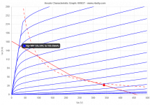
The attached page from the STC Apllication Report for the 807 from 1954 shows that you can get 80 Watts at Va = 600 V and Raa = 6400 Ohm from a pair of 807's in class AB2. So I don't understand why you seem to write that an Raa of 3445 Ohm is essential.
The giant beasts:-
5225ohms A-A 825V HT - makes 125W.
(like incredibly low for such a high voltage)
Same manufacturer:- (I have a brand new one of these never used)
11835 ohms A-A 350V HT - 6V6 makes 10-12W in AB1.
I have extensively tested the performance of the amp, & people love the sound.
Personally it's not my cup of tea and the FR is obviously extremely coloured when tested.
I use a nominal 6k6 A-A load for my own (Ab1) design of PPP valve amp with Va of 460V.
It is the result of 3yr's study to come up with a design that surpasses anything I could ever see anywhere in the world, and sounds fantastic.
In reality it gives best performance at a match of 4750 ohms. (ie. 16ohm secondary into 10 ohms load).
That's 50W from 2 parallel pairs of 9W pentodes, physically much smaller than the EL84, with vanishingly low distortion, no UL in sight, and no loop feedback.
The output transformers are from 1963.
It's impossible to give a meaningful reaction without knowing what tube types are involved.
Attachments
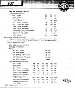
The attached page from the STC Apllication Report for the 807 from 1954 shows that you can get 80 Watts at Va = 600 V and Raa = 6400 Ohm from a pair of 807's in class AB2. So I don't understand why you seem to write that an Raa of 3445 Ohm is essential.
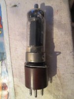
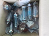
I am perfectly aware of what STC claims, but unlike you I have about 20 of them.
(5B254M) all brand new and tested+selected into matched pairs and even quads.
Here is one under test, using my special little adaptor.
What you may not understand is how PSU flex heavily under load in Ab2.
The currents are considerably higher.
So, if you have an AB2 amp, in actual fact using the original type of PSU you are likely to see the anode voltage sag to as low as 425V, at which point the A-A load I quoted is quite correct.
Good OEM constructors of the 50s and 60s understood this perfectly, which is why to avoid clipping (obvious at the high distortion levels shown on the document you quoted), they tweaked things to produce as good a performance as was possible....
However when you test and run things in real world conditions, the STC docs are only a guide.
In reality in the original configuration of that amp, it was dirty at under 15-20W, and was really horrible at the rated 50W output.
After a considerable redesign, I could get a genuine clean 70-75W, but which included raising the HT line to 600V, stabilising the screen with a shunt stabiliser, stabilising the bias supply with zeners, and preventing HT sag by using silicon rectifiers, all pretty way beyond what STC were able to do in 1950.
Manualitis is a condition easily solved by working on real amplifiers, not second guessing stuff with "computer generated" load lines, and with no regard at all for the massive production spread of NOS valves from 50-60yrs ago...
Ask me how I know.
Attachments
...actually a HF transmitting valve...
Attachments
A couple of 'ad hominems', some bragging, and the ludicrous claim that engineers in the fifties could not prevent a power supply under load sagging from 600 V to 425 V. That's pretty much it.
No reaction on the second part of post #32, just like there still is no reaction on most of post #30.
No reaction on the second part of post #32, just like there still is no reaction on most of post #30.
How many of those 1950s amplifiers do you actually own Mr PFL?the ludicrous claim that engineers in the fifties could not prevent a power supply under load sagging from 600 V to 425 V. That's pretty much it.
Just a straight answer please.
did I actually say it sagged from 600V to 425V?
(I replaced the PT on it to get more current and to convert from 110V > 230V EU power).
In your hurry to diss everything you fell over, because it originally measured 520V at idle, and fell to 420V under full load, however as is the case on good quality PA of such years, it has a screen supply drawn not from a chain of resistors, but from a seperate winding on the PT...**
I have quite a few, some of these beautifully restored, inc 2 identical pairs of 50W AB2 amps, and an identical pair of the 125W model.
As far as I am aware nobody else in the world has that.
Have you ever tested such a thing?
Measured the power supply voltage drop from idle to full power into a dummy load.
I don't think so.
Btw,-
**The 125W amp has a seperate transformer for heaters + screen supply, and a basic bias and a screen supply regulator.
I also have an identical pair of the MO200 Bogen amp, which Dave Gillespie decribed in great detail, - showing how to turn it into a magnificent stereo amp, as well as about a dozen of the various other 8417 based amps which run basically class B to Ab1.
Do you have any of these 1960s amps, with those magic Westinghouse valves?
Of course not.
Btw2.
The Bogen MO200*** has such a powerful PSU it's able to manage 190W RMS without breaking a sweat & run 24/7/365 for decades on end.
It runs parallel push pull ( a total of 8 output valves), just as I have been suggesting to do here with the 6V6, because in PPP it will work beautifully.
***It's reckoned to be as good as Fisher SA1000 or better once tweaked, and in a different league from Quicksilver...
The Fisher SA-1000 is a legendary tube amplifier - right up there on the "Holy Grail" list of HiFi pieces that every audiophile must own at some point..
and
The Quicksilver 8417 mono blocks are some of the the finest amplifiers ever made. They have a marvelous, true classic tube sound. And the 8417 tube is a special kind of tube with a huge warm sound and wonderful detail and nuances of vocals, instruments and low end extension. No other tube sounds quite like the 8417 tube.
Do you have a better idea?
Last edited:
May I?
When I did R&D, part of my job was being the interface with inventors of different parts of the world. Everyone was the chosen one, everyone was legitimated to rewrite all laws of physics, everyone was the only owner of the real Truth (with capital letter) and everything else was wrong, even when it worked.
Everyone of us has his defects, as well as everyone can apport interesting developements to others.
I was the person to interface with the inventors because I'm patient, empathetic, curious and sorta intuitive (in variable order).
Most other people just see this selfish behaviour and go away or inevitably fight, my approach was to find what was interesting and bring the discussion to it (the idea, or realisation of it), find possibilities of collaboration on that specific topic a reasonable explication.
Sarcastic1, you have some of the elements of those inventors. ты изобретатель?
May I suggest to open a specific thread talking about those beauties, and discuss about them and their approach on AB2 in that new thread? I would be pleased to know more about it without going off topic in this specific thread about 6P6S. It would also most probably reset everyone's mood.
Thanks
It seems that Sarcastic1 knows what he is talking about but tends to talk in absolutes rather than in a more nuanced tone. Regarding the AB2 vs AB1 load, to get the higher power possible with AB2, the load should be reduced or the voltage increased keeping the same load. Using the 807 example for AB1 360V plate, 270V screen power is 26.5W with 6.6k load. AB2 with the same voltages power is 47W with 3.8k load (around about half the load like Sarcastic1 says but not exactly). Alternatively you can keep the ~6.6k load and raise the voltage to 600V plate 300V screen and get 80W.
Previous comments about 6V6 not being suitable for UL operation perhaps should be read as 6V6 being less suitable than other tube types for UL operation. It's easy to get annoyed by the language used sometimes, but as Zintolo says, it's a better approach to pick out the good ideas instead.
Previous comments about 6V6 not being suitable for UL operation perhaps should be read as 6V6 being less suitable than other tube types for UL operation. It's easy to get annoyed by the language used sometimes, but as Zintolo says, it's a better approach to pick out the good ideas instead.
Nothing to do with absolutes.Sarcastic1 knows what he is talking about but tends to talk in absolutes rather than in a more nuanced tone. Regarding the AB2 .......Alternatively you can keep the ~6.6k load and raise the voltage to 600V plate 300V screen and get 80W.
Problem with all this theoretical stuff is, it doesn't work out in practice.
I test stuff in the toughest possible conditions - full power, square wave, Frequency response at full power 20hz into a dummy resistive load and inductive loads too.
eg.
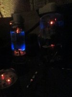
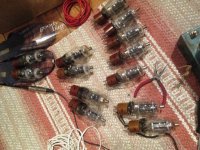
I tested a whole pile of brand new 807 (STC 5B25xx).
2 of them produced arcs on turn on, so were immediately rejected.
You can see the production spread, as the current is marked on the loctal collars in felt tip...on an amp with fixed bias.
2 marked "S" for strong (value 260) means 260mV over a 4.7Ohm cathode resistor.
(0.055A at 580V) or 32W..
..leave that on long and it will melt.
One is marked "180" = 38ma which is 22W. (within the 25W anode rating), and about right for the amp at idle.
Here are some of the original 807s about a dozen of them.
2-3 of them red plated, 4-5 of them had low emissions and if you are lucky you might get 2 pairs that actually match. Some were as low as "0.135" - 29ma 16.5W!
This is quite normal.
The production spread of NOS valves is all over the place.
I have more than 250 of one particular type, which go from anything between 7ma (3.25W) to 18ma at idle at 460V (8,25W), and these are GEC NOS original mil spec types.
All very well to talk of 80W, but it doesn't work out in practice.
Instead you get that horribly distorted waveform at about 60W.
It took a lot of work to get that amplifier to run clean at anything over 30W, and a real redesign to get it to make 75W with a proper clean waveform and low THD.
The 6V6 amplifiers I worked on, claimed also 12W each with low distortion and good bandwidth.
In practice they weren't anything like clean after 8W, and ran into obvious OPT saturation below 35hz at full power.
6V6 running in cathode bias, is a whole can of worms, and produced lots of distortion.
I can't see the point trying to run such stuff UL on 6V6 because the gain is so low, and the thing is obsolete.
You can get a 19W version of thing for peanuts.
+
I wouldn't touch such stuff again unless it was running in fixed bias, with a matched QUAD of them, and that would have to be the 6HE5 or 6JB5 or 6CJ5, all much better versions of the 6V6 anyhow, which the USSR never had.
Like this thing.
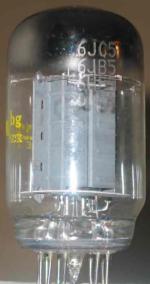
Attachments
Last edited:
I'm trying to figure out how a 6JC5 is a newer/better version of a 6V6GT.
6V6GT characteristics and typical operation:
Heater 6.3V 0.45A <--
Plate voltage 250V
Grid 2 voltage 250V
Grid 1 voltage -12.5V <--
Plate current 45mA
Transconductance 4.1mA/V
Plate resistance (approx) 50k ohms <--
Ec1 Voltage for Ib = 100uA (approx) not stated
6JC5 characteristics and typical operation:
Heater 6.3V 0.8A <--
Plate voltage 250V
Grid 2 voltage 250V
Grid 1 voltage -20V <--
Plate current 43mA
Transconductance 4.1mA/V
Plate resistance (approx) 50k ohms <-- ("5000 ohms" was a typo on Sylvania data sheet)
Ec1 Voltage for Ib = 100uA (approx) -50V
They're similar, true, but they are different enough beam pentodes. If you like 6JB5/6JC5 better, that's great. But it does require a lot more drive voltage at the same operating conditions, and it also requires more current from its heater supply. Those are important differences in the situations where 6V6 is normally used (small low power amps).
Last edited:
- Home
- Amplifiers
- Tubes / Valves
- Soviet 6V6 tube question