Dry fitting
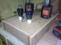
Have come to the part where dry fitting is needed to..... just for the fun of it.
Have been stacking components, tubes, transformers and all the needed things now for a year +, so now I want to know what it will be when put together.
I also want the chanse to foresee eventual problems before starting on the aluminium plate, paint work and final assembly.
Furthermore I wanted to evaluate different positions of the transformers since they, if put too far back will make the amplifier very unbalanced so I have tried to find an optimum by moving them towards the front as much as possible without disturbing the final look and still get a fairly balanced amp. We are talking about 16-18 kg (36-38 pounds) finished amp so I don't want it too unbalanced since it will be ponderous as it is.
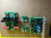
Bazelio; You got the answer from tomchr who is also the developer of the Damn Good 300B. I have choosen to use caps at the moment cause I did find the input transformers very expensive...(in a still, expensive project anyway) so right now I go for the caps since I had them laying around but when things start producing music we'll see, could be that I make the investment if needed.../ wanted.
Just as a paranthesis, this build is by far the most expensive that I have ever started within DIY. Right now my budget is close to $1700 in parts only and that doesn't include the transformer from Lundahl that I have decided to let go in favour for the Classictone.
Have come to the part where dry fitting is needed to..... just for the fun of it.
Have been stacking components, tubes, transformers and all the needed things now for a year +, so now I want to know what it will be when put together.
I also want the chanse to foresee eventual problems before starting on the aluminium plate, paint work and final assembly.
Furthermore I wanted to evaluate different positions of the transformers since they, if put too far back will make the amplifier very unbalanced so I have tried to find an optimum by moving them towards the front as much as possible without disturbing the final look and still get a fairly balanced amp. We are talking about 16-18 kg (36-38 pounds) finished amp so I don't want it too unbalanced since it will be ponderous as it is.


I'm wondering about the input isolation transformers. I may just go with caps there as I'm not doing balanced or differential input, just RCA. Thoughts?
Bazelio; You got the answer from tomchr who is also the developer of the Damn Good 300B. I have choosen to use caps at the moment cause I did find the input transformers very expensive...(in a still, expensive project anyway) so right now I go for the caps since I had them laying around but when things start producing music we'll see, could be that I make the investment if needed.../ wanted.
Just as a paranthesis, this build is by far the most expensive that I have ever started within DIY. Right now my budget is close to $1700 in parts only and that doesn't include the transformer from Lundahl that I have decided to let go in favour for the Classictone.
Advise pls!
I would like to ask the readers/DIY:ers here a small but important question.
Tube base, should it go above the surface of the top plate or can I allow it to sit down through the top plate??
I presume the tube base will get pretty hot when operating so if I let the tube base go down through the top plate then, is it enough to let some space (1-2 mm) between the top plate and the tube base or would it recuire some massive aeration around the base?
Since I have never built a tube amp and only picture references I want to ask someone who have actual experience.
Tube base, should it go above the surface of the top plate or can I allow it to sit down through the top plate??
You could consider using one of the vented plates designed for the purpose. VT4C has a bunch.
The tube base doesn't get that hot. I still wouldn't let it get into contact with the wood, though. You'll also need a gap so you can get the tube in there to begin with. I probably wouldn't cover more than half the tube base height. That's purely a guess, though.
Also remember that you need access to the tube base to pull the tube. Never pull a tube by the glass envelope!
If you've never built a tube amp, Morgan Jones' book on building tube amps is a worthwhile read. It's pretty inexpensive too.
Tom
Help needed!
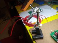
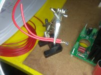
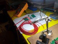
Hi all, need to ask a question of some importance.
I will start hooking up wires and I found that the metalclip don't manage two entering cables since I will be using 1.5 mm2 and then I know that I can fix it by cutting of about half the wire area and then manage two wires in one clip.
Now the question, if I cut away half of the wire area how is this affecting current??
A general thumb is that you can have about 10 amps per square mm cable so that would mean that I still can use them for about 5 amps (only need 2.5 amps max). I know that it is not correct (and it doesn't look good) to do so but otherwise I have some problem fitting the wires and have to make some other kind of connection.
If I will run 1.5 to 2.5 amps maximum how far down in size can I go?? I also have 0.2 mm2 at home but I think that will be little to weak. Maybe I can get 0.75 mm2 today otherwise I have to wait until monday.
I think you may be taking the top level hookup schematic a little too literally. The two Universal Filament Regulators for the 5.0 V supplies are fed from the same terminal block on the DG300B PSU board. I suggest making two identical harnesses and just run two wires into the rising cage clamp terminal blocks of the PSU board rather than trying to jam two wires into the crimp terminals. I do see the ambiguity in the design doc and will fix that.
Sorry about the confusion there.
Tom
Sorry about the confusion there.
Tom
Tired!!
Tom, sorry for the stupid question.
I was pretty tired when sitting with it th other day after a full day in the city. Was thinking that I had contacts on both sides and would have have problem however I did it. Didn't even concider the Euroblock on the other end, mea culpa! Fixed it yesterday myself.
Good lesson though, don't be tired when fixing tube amps, you could get a pretty rough wake up if it is live.
Ok, it has been summer and family time has been frequently interupting my building time so things have not advanced as I would have liked....
but I have had a nice summer anyway.
I have not spent so much time thinking in my DG 300B either cause I have come so far now that is time to start things up and test it and since I don't own a variable transformer I had to make myself a Dim Bulb tester
 .
.
I did not intend to go and buy these things so it took me some time to collect the things, or to be true, it took me some time to find a porcelain socket for the lamp. Now it is here and since I had time yesterday to go to the basement I decided to put it all together. I have to find a ordinary lamp bulb also cause all I had at home was a special lamp with real carbon filament and that one I will not use for the tester, it was just to see so everything was working as it should.
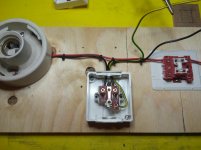
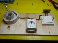
Well, that mean that now I will aim to get some sound out of my amp as soon as time allow me to work and...... today is a good day to start.
but I have had a nice summer anyway.
I have not spent so much time thinking in my DG 300B either cause I have come so far now that is time to start things up and test it and since I don't own a variable transformer
I did not intend to go and buy these things so it took me some time to collect the things, or to be true, it took me some time to find a porcelain socket for the lamp. Now it is here and since I had time yesterday to go to the basement I decided to put it all together. I have to find a ordinary lamp bulb also cause all I had at home was a special lamp with real carbon filament and that one I will not use for the tester, it was just to see so everything was working as it should.


Well, that mean that now I will aim to get some sound out of my amp as soon as time allow me to work and...... today is a good day to start.
Back in buisness......
I started connecting cables yesterday and preparing the OPT so that they can be used with my amplifier but I ran into a question that I did not figure out myself.
On the primary side of the Lundahl 1623 it is no problem, rather straight forward so to say but on the secondary side I became doubful how to connect them.
I need some help to read the info in the paper below.
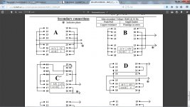
For the use with a single end amplifier it is only scedule B and C that apply for 90 mA version but witch to use, that is my question??
what are the different voltages referring to and how do I know which schematic to use and why is it so??

If someone here can shine some light on this matter I would appreciate it a lot. I am stomping on the same spot now cause I want to at least test the power board for faults this weekend.
The rest should then be up and tested/running during next week and if everything work out I think I can manage the plint and aluminium work before Christmas and that would be like...... Christmas!

I started connecting cables yesterday and preparing the OPT so that they can be used with my amplifier but I ran into a question that I did not figure out myself.
On the primary side of the Lundahl 1623 it is no problem, rather straight forward so to say but on the secondary side I became doubful how to connect them.
I need some help to read the info in the paper below.

For the use with a single end amplifier it is only scedule B and C that apply for 90 mA version but witch to use, that is my question??
what are the different voltages referring to and how do I know which schematic to use and why is it so??
If someone here can shine some light on this matter I would appreciate it a lot. I am stomping on the same spot now cause I want to at least test the power board for faults this weekend.

The rest should then be up and tested/running during next week and if everything work out I think I can manage the plint and aluminium work before Christmas and that would be like...... Christmas!
According to Page 3 of the Lundahl 1623 data sheet, you should use connection B for 5.6 kΩ primary impedance at 8 Ω load. At least that's how I interpret it.
Tom
Tom
tmchr, you are absolutely right in your interpretation.
Since I am doubtful, always, and since I did not understand the data in the pdf I had to ask. I am normally rather good at intepreting this kind of papers but this time a needed a second hand opinion, furthermore I couldn't ask Lundahl themselfes yesterday due to the late hour.
That is why I now, when I see your answer tomchr can confirm the answer, I called Per Lundahl in the morning hour.
It is as you interpreted that B is for 8 Ohm and C is for 16 Ohm! Per at Lundahl said that it was a little cryptical since the data sheet cover 4 different transformers with 16 different configurations so it is not a easy task to get all that information in one data sheet , but now we/I know.
Ok, on to work then..... (and unfortunately some real work also)
Since I am doubtful, always, and since I did not understand the data in the pdf I had to ask. I am normally rather good at intepreting this kind of papers but this time a needed a second hand opinion, furthermore I couldn't ask Lundahl themselfes yesterday due to the late hour.
That is why I now, when I see your answer tomchr can confirm the answer, I called Per Lundahl in the morning hour.
It is as you interpreted that B is for 8 Ohm and C is for 16 Ohm! Per at Lundahl said that it was a little cryptical since the data sheet cover 4 different transformers with 16 different configurations so it is not a easy task to get all that information in one data sheet
Ok, on to work then..... (and unfortunately some real work also)
OPT
Ok, yesterday evening I fixed the OPT so that they are ready to connect and I think I got it worked out fairly neat.
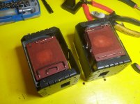
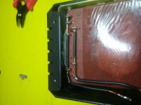
I'll see if I have time to start connecting the main transformer tonight so that I can test the power supply tonight or tomorrow. I have been reading the sticky about safety working with HV so if it gets too late.... better wait til tomorrow, don't work when tired.
After reading about the safety I re-arranged my work table so that I can probe with one hand and still have main switch available on the bulb tester available for the other hand.
Ok, yesterday evening I fixed the OPT so that they are ready to connect and I think I got it worked out fairly neat.


I'll see if I have time to start connecting the main transformer tonight so that I can test the power supply tonight or tomorrow. I have been reading the sticky about safety working with HV so if it gets too late.... better wait til tomorrow, don't work when tired.

After reading about the safety I re-arranged my work table so that I can probe with one hand and still have main switch available on the bulb tester available for the other hand.
Testing, testing!!!
A little dissapointed..... but not without hope!
Now I need some advice and help here.
I connected the power board today to the main transformer according to the specs, connected my light bulb tester board to mains and then the transformer gets connected via the power board to the light bulb tester.
Before hitting the switch I went through everything once more and then.....
power!
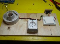
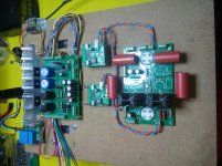
I saw that the green diode connected to the board (on/off) did not ligth up but I saw that the red once ligthed up telling me that the caps did charged up and then.....
things did happend and smoke was rising from the power board!!

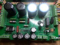
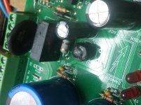
The bridge rectifier did give in and from what I can tell it is only the rectifier that have burnt.
Honestly, I just left it for the evening so I will have to go through things more thorough tomorrow. I just checked that everything was cool and not a danger for the house before leaving it in the basement this evening. I thought that everything should go so easy and it should only be to connect everthing and then listen to music but HA......... not this one!
I might have been doing something stupid and I missed the part that I should use a 25W bulb in the bulb tester but I had 60W lamp bulb in, can that affect the start up?
Don't think so, it is just a matter of how much the bulb will light up and the only thing that I can imagine I have missed by using a 60W bulb is that it in fact was an error on the board and with a 25W bulb I would have noticed emediately by the light.
I also noticed that the famous click from the relay did not occur, that is also something that make me think that I have an error on the board. I will check tomorrow but I really don't know really where to start so advices here would be appreciated.
On the other hand.... I hopefully get away with some minor changes of components and then we go again and I am very happy for tomchr:s good advice to NOT connect everything from start but to in fact test it bit by bit.
A little dissapointed..... but not without hope!
Now I need some advice and help here.
I connected the power board today to the main transformer according to the specs, connected my light bulb tester board to mains and then the transformer gets connected via the power board to the light bulb tester.
Before hitting the switch I went through everything once more and then.....
power!


I saw that the green diode connected to the board (on/off) did not ligth up but I saw that the red once ligthed up telling me that the caps did charged up and then.....
things did happend and smoke was rising from the power board!!


The bridge rectifier did give in and from what I can tell it is only the rectifier that have burnt.
Honestly, I just left it for the evening so I will have to go through things more thorough tomorrow. I just checked that everything was cool and not a danger for the house before leaving it in the basement this evening. I thought that everything should go so easy and it should only be to connect everthing and then listen to music but HA......... not this one!
I might have been doing something stupid and I missed the part that I should use a 25W bulb in the bulb tester but I had 60W lamp bulb in, can that affect the start up?
Don't think so, it is just a matter of how much the bulb will light up and the only thing that I can imagine I have missed by using a 60W bulb is that it in fact was an error on the board and with a 25W bulb I would have noticed emediately by the light.
I also noticed that the famous click from the relay did not occur, that is also something that make me think that I have an error on the board. I will check tomorrow but I really don't know really where to start so advices here would be appreciated.
On the other hand.... I hopefully get away with some minor changes of components and then we go again and I am very happy for tomchr:s good advice to NOT connect everything from start but to in fact test it bit by bit.
It looks like you've installed the li'l rectifier backwards. You're off by 90 degrees. There's a flat side on the rectifier package. This flat needs to line up with the corresponding flat side of the legend on the silk screen (facing R11). Just swap out the rectifier and you'll likely be fine.
Tom
Tom
Last edited:
It looks like you've installed the li'l rectifier backwards. You're off by 90 degrees. There's a flat side on the rectifier package. This flat needs to line up with the corresponding flat side of the legend on the silk screen (facing R11). Just swap out the rectifier and you'll likely be fine.
Tom
Seem reasonable cause I had some short time to make some readings with my DMM before the smoke started oozing and I couldn't get stable readings on the secondary side, it was jumping up and down all the time indicating a faulty direct current.
Have to wait a couple of days cause my local supplyer only have rectifiers managing 600 VDC but at least it was not the expensive parts burning.


Now when I have the power board off for repair then I must ask another question, I have it jumped for 230VAC usage but question is, should I make that 240V instead and is there any harm in having it one way or the other?
Officially we run 240VAC nowdays in Sweden and the tranformer I use is rated 2 x 115V and if I measure incoming AC I have 230V so what is the correct way of jumping the board?
If the nominal mains voltage is 240 V, you should configure the board for 240 V operation. If you set it for 230 V operation, you risk frying the filament regulators if the mains voltage is higher than nominal one day.
For the li'l rectifier, you can use a lower voltage type. A 50 V type would work just as well as the one I'd specified. It only drives a soft start relay and an LED. That style of rectifier is called WOG. W005G - W10G all work in the board.
Tom
For the li'l rectifier, you can use a lower voltage type. A 50 V type would work just as well as the one I'd specified. It only drives a soft start relay and an LED. That style of rectifier is called WOG. W005G - W10G all work in the board.
Tom
Now when I have the power board off for repair then I must ask another question, I have it jumped for 230VAC usage but question is, should I make that 240V instead and is there any harm in having it one way or the other?
Officially we run 240VAC nowdays in Sweden and the tranformer I use is rated 2 x 115V and if I measure incoming AC I have 230V so what is the correct way of jumping the board?
If the nominal mains voltage is 240 V, you should configure the board for 240 V operation. If you set it for 230 V operation, you risk frying the filament regulators if the mains voltage is higher than nominal one day.
Tom
Ok, did some reading about what we have and not as incoming VAC and as I conclude the information I am right having it jumped for 230VAC.
Before Sweden had 220 VAC 50Hz (when I was a kid (up to 1988)) but slowly they bumped it to closer 230 VAC, and that is what I measure also on the wall plug. But, and here is the but(t) as Europe as total have agreed to have the same electrical standard (even England that usually have to run their own standards (no offence to anyone I hope)) all devices used have to be usable up to 240VAC and that is what is stipulated as a minimum requirement for all electronical devices used in Europe, therefore the confusion and my question.
As we are running 230VAC I have it correctly jumped for the moment but in the future maybe I have to re-jump it if someone in the big companies producing our electricity, get the idea to bump it even closer to 240VAC since they have that possibility if they want, within the actual standard. Ok that day, that sorrow.
Tnx for your answer tomchr. worth a lot since I can get my WOG:s today and don't have to wait until next week.
Testing, testing 2!!
Ok, things are at least not on fire this time!

All voltages seem ok except for the 300B+ voltage that is on the low side. I should have appr. 525 volts but only have 485 volts, also after 25 minutes running. Hmmmm!! Filaments should be around 20V and they are appr. 28V, the bias should be -225V and is -229V so fairly ok I would say but the B+.....?
Since there are not many components involved for the 300B+, two caps, two resistors and a led, I can only suspect that the tranformer is not delivering correctly (will check that during the evening, can be that I have to switch some cable but I have followed tomchr:s information, that is also accordingly to Classic Tone drawing, to the point here but will double check anyway since I have both 330V and 380V on that secondary depending on connection). In other case I have to manipulate the two resistors involved. Noticeable is that the led (LED2) is burning a little brighter than LED10 that is also monitoring charge on the reservoir capacitors but for the bias. My symetrical mind want the two leds to burn equally bright but that is only me, not the schematics, it can be me, fooling myself.
tomchr, by the way, I did mess up the rectifier all by myself!!

I remember that I was in doubt of the correct direction of the rectifier since one of the sodering pads is square and that is normally plus when talking about diods and caps. There I was having the silk screen saying one direction and the soldering pad saying "hello, plus here please" therefore the mistake. I could have turned the PCB around and verified the right correction but never did, stupid me.

Ok, things are at least not on fire this time!
All voltages seem ok except for the 300B+ voltage that is on the low side. I should have appr. 525 volts but only have 485 volts, also after 25 minutes running. Hmmmm!! Filaments should be around 20V and they are appr. 28V, the bias should be -225V and is -229V so fairly ok I would say but the B+.....?
Since there are not many components involved for the 300B+, two caps, two resistors and a led, I can only suspect that the tranformer is not delivering correctly (will check that during the evening, can be that I have to switch some cable but I have followed tomchr:s information, that is also accordingly to Classic Tone drawing, to the point here but will double check anyway since I have both 330V and 380V on that secondary depending on connection). In other case I have to manipulate the two resistors involved. Noticeable is that the led (LED2) is burning a little brighter than LED10 that is also monitoring charge on the reservoir capacitors but for the bias. My symetrical mind want the two leds to burn equally bright but that is only me, not the schematics, it can be me, fooling myself.
tomchr, by the way, I did mess up the rectifier all by myself!!
I remember that I was in doubt of the correct direction of the rectifier since one of the sodering pads is square and that is normally plus when talking about diods and caps. There I was having the silk screen saying one direction and the soldering pad saying "hello, plus here please" therefore the mistake. I could have turned the PCB around and verified the right correction but never did, stupid me.
- Home
- Amplifiers
- Tubes / Valves
- New project, Damn Good 300B amp.