I recently built a zero global feedback Unity-Coupled amp, which was a real challenge. Obviously, the big challenge is developing huge voltage swings for the driver stage with really low distortion. The output stage itself doesn't distort much, and input stages aren't that hard to do well. I ended up using a CCS loaded 841 in A2 for the driver but I think an 801A would have worked equally as well. The problem is that these tubes are expensive if you can even get your hands on them.
I got to thinking that it would be fun and even more challenging to make a cathode follower SE amp some day, but I really don't see new production or cheap old tubes that are good candidates for the driver. I don't want to have to hoard rare tubes to keep my amp running (like I am doing for my amp now).
Then I got to thinking about an amp that I made for my brother where I used a little local plate-grid feedback on a KT88 (using a p-channel fet) and got better results than a lot of open-loop 300B amps. I got to thinking that if I CCS-loaded a tube with that same feedback scheme (and buffered that feedback to avoid loading down the CCS), I might be able to achieve very high voltage swing at very low distortion, enough to drive a CF output stage.
If I were going to use it as a driver for a CF amp, I would need a tube that could handle a high quiescent plate voltage and high-ish transconductance would give good linearity/low rp after the local feedback is applied. EL34 seemed to be a good (and inexpensive) candidate.
I have attached the drawing of the circuit and am currently breadboarding this up. I'll post measurements as I get them.
I'm thinking that bias stability might be an issue with this. I don't know how much drift with temperature that there will be with the EL34, but I think the final solution will contain a bias servo to keep things running just right all the time.
Please excuse the fact that some of the mosfet symbols and zener diodes are not correct. I was doing a board layout, got lazy, and just grabbed parts that had the correct footprint. I hope my labels will make it clear what is going on.
Attachments
Nice idea. I played with a similar design time ago for an 1624 Schaded output stage. The trouble is that the top FET needs to swings at the anode voltage +25V headroom to operate well. In a SE (or PP) stage will require an extra supply. For example when I had the output valve biased at about 400V (and HT was 410-420V) I needed +600V for full swing when FB was about 15-20%. An extra supply, low current as only needs grid current support. I think I used about 8-10mA per driver. Top FET was a IXCP10M90S. I could reduce the distortion of the stage significantly from 1% @ 4W down to 0.35%. Mainly H2 reduction though, H3 didn't reduce as much.
In your design, providing the CCS has full swing capability, you won't need an extra supply, so nice approach in my view.
Cheers
Ale
In your design, providing the CCS has full swing capability, you won't need an extra supply, so nice approach in my view.
Cheers
Ale
Years ago I built a few amps using a cathode follower output stage. Many of these used a 6EM7 dual triode as a driver with some ridiculous B+ voltage feeding the low Mu section. It all worked, but then I discovered the "augmented cathode follower" which was patented in the mid 50's. It is a circuit design intended to remove all the flaws in a simple cathode follower circuit, and was intended for small signal operation. I discovered two important things, it makes a killer output stage, and it can be operated with gain due to the feedback loop. My simulations showed that stage gains up to 5 were possible, but the best I could get in a working amp was about two. These were all tube circuits, so you could probably do better with an injection of sand in s few places. A power cathode follower with a gain of 2 makes things easier, although more complex.
See this thread:
http://www.diyaudio.com/forums/tube...wer.html?highlight=augmented+cathode+follower
See this thread:
http://www.diyaudio.com/forums/tube...wer.html?highlight=augmented+cathode+follower
Nice idea. I played with a similar design time ago for an 1624 Schaded output stage. The trouble is that the top FET needs to swings at the anode voltage +25V headroom to operate well. In a SE (or PP) stage will require an extra supply. For example when I had the output valve biased at about 400V (and HT was 410-420V) I needed +600V for full swing when FB was about 15-20%. An extra supply, low current as only needs grid current support. I think I used about 8-10mA per driver. Top FET was a IXCP10M90S. I could reduce the distortion of the stage significantly from 1% @ 4W down to 0.35%. Mainly H2 reduction though, H3 didn't reduce as much.
In your design, providing the CCS has full swing capability, you won't need an extra supply, so nice approach in my view.
Cheers
Ale
Well, the high voltage power supply could be a bit of a problem. I am using 900V mosfets at the moment so I can't go over 900V and I could see having the supply be 1000V necessary, depending on the amp design. Right now, I'm just breadboarding to take some measurements. First round of tests will be with a 400V supply. I just want to see if turning the EL34's tranconductance into linearity via the feedback will work as well as I think it will.
But the necessity of all of the extra supplies is a definite disadvantage. Compare that to the simplicity of choke loading an 801A and running that from the same supply as the output tube.
If I were to build an amp for this, I'd do a separate power transformer for the driver stage and output stages.
Years ago I built a few amps using a cathode follower output stage. Many of these used a 6EM7 dual triode as a driver with some ridiculous B+ voltage feeding the low Mu section. It all worked, but then I discovered the "augmented cathode follower" which was patented in the mid 50's. It is a circuit design intended to remove all the flaws in a simple cathode follower circuit, and was intended for small signal operation. I discovered two important things, it makes a killer output stage, and it can be operated with gain due to the feedback loop. My simulations showed that stage gains up to 5 were possible, but the best I could get in a working amp was about two. These were all tube circuits, so you could probably do better with an injection of sand in s few places. A power cathode follower with a gain of 2 makes things easier, although more complex.
See this thread:
http://www.diyaudio.com/forums/tube...wer.html?highlight=augmented+cathode+follower
Thanks, that's something to look at. I think I had read something about it elsewhere but never actually looked into the circuit.
The Unity-Coupled output stage is essentially a mu=2 configuration. A lot of the drive behind this experiment is simply to see if I can conquer a bigger voltage swing requirement (and to see if this would be a good upgrade path for the UC amp when I eventually run out of 841s), not so much that it would be the best rational choice for maximizing an amp's performance. I'm just climbing this mountain to see if I can.
Will this circuit configuration eventually get me to the 900V pk-pk swing area with relatively low distortion? We'll see. The lack of 1000V+ depletion fet parts may make that difficult.
I remember when I simulated the circuit (with a CCS) I found a peak at above 2MHz and phase was 180 which alerted me from oscillations. I added a 33pF cap between anode and gate to create a pole around 300kHz. Worth looking into the stability of the stage before embarking yourself in any PCB stuff. Just my two pennies..
Cheers
ALe
Cheers
ALe
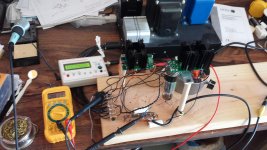
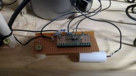
I'm wiring it up using a couple of PCBs I had previously made that offer the necessary building blocks. I won't have a PCB specially made for this unless that testing goes well. I'll post pictures and measurements when I get there. I'm a slow worker so it may be a little while. I have the PCBs built up and am in the process of mounting and wiring up the breadboard.I remember when I simulated the circuit (with a CCS) I found a peak at above 2MHz and phase was 180 which alerted me from oscillations. I added a 33pF cap between anode and gate to create a pole around 300kHz. Worth looking into the stability of the stage before embarking yourself in any PCB stuff. Just my two pennies..
Cheers
ALe
Last edited:
I would bootstrap the driver tube, by an ordinary C-R, from cathode, if to drive a tube. The result would be "SRPP"-ish.
Speaking of augmented followers, I tried one with SemiSouth JFET followers. Sound was superb, but too much heat. 🙂
Speaking of augmented followers, I tried one with SemiSouth JFET followers. Sound was superb, but too much heat. 🙂
I would love to see the masterpiece you built.
It is a beautiful amp.
Thanks, that's something to look at. I think I had read something about it elsewhere but never actually looked into the circuit.
The Unity-Coupled output stage is essentially a mu=2 configuration. A lot of the drive behind this experiment is simply to see if I can conquer a bigger voltage swing requirement (and to see if this would be a good upgrade path for the UC amp when I eventually run out of 841s), not so much that it would be the best rational choice for maximizing an amp's performance. I'm just climbing this mountain to see if I can.
Will this circuit configuration eventually get me to the 900V pk-pk swing area with relatively low distortion? We'll see. The lack of 1000V+ depletion fet parts may make that difficult.
It is a beautiful amp.
Here is an idea.
HV Mosfet cascode with N Fdbk to the triode plate (thru Mosfet Gate to Source).
Triode could be a high gm 12HL7 in triode mode. Or maybe an E55L/8233 for $$$.
HV Mosfet cascode with N Fdbk to the triode plate (thru Mosfet Gate to Source).
Triode could be a high gm 12HL7 in triode mode. Or maybe an E55L/8233 for $$$.
Attachments
Last edited:
Now I'll have to scratch my head for a while and figure out how that works.
As far as your comments go on the other thread, many other tubes should be possible. I chose the EL34 because it was cheap and I had one other concern. Since this was going to be operated at lower currents and with a CCS load, I was concerned that a lot of beam tubes have negative slopes in the characteristics at low currents and low plate voltages. The pentodes don't seem to have that as much, especially with lower screen voltages.
Once I get it working I can sub other tubes. It might make a really linear first stage as well with an EL84 or other smaller sized tube.
I just thought of a nice improvement on the previous HV Cascode N Fdbk driver.
By moving the top of R1 (of the N Fdbk attenuator R1, R2) up to the bootstrap signal point, coming from the CFB output stage cathode, the circuit then controls the CFB stage cathode V to be
CFB cathode V = Mu x (R1+R2)/R2 x Input V
(instead of controlling the CFB stage grid V as before)
Just more effective use of the N Fdbk that way. And that keeps the R1, R2 attenuator current out of the equation (or out of the floating CCS current, if that is used)
I'm really liking this circuit now. A programmable HV high gm triode. (that even fixes any non-linearity of the output tubes)
One could turn this into a differential version too. Just use two circuits, with a CCS tail under them. (the tube cathodes connected) Probably have to put Gyrators up top then, instead of CCSs. Ehhh, could just use the simple bootstrapped RL loads up top then. They are close enough to constant current. The differential triode tube base can handle a tiny amount of current variation linearly anyway.
.
Last edited:
Ack!
The edit function let me delete the previous file, but timed out on the new file (for above).
Here is the amended HV cascode N Fdbk driver schematic. Might want to move R1 (top) over to the left side of Cboot, depending on how DC levels are set up in the Amp. Alternatively, the bottom of V1 could be moved to a negative supply.
Attachments
Last edited:
Alright, I fired up the prototype today. I expected plate voltage to wander a bit as the tube warmed (because the high gain of a CCS-loaded pentode) but was surprised to see it stay stable within a few volts for 20 minutes or so. Final circuit will probably include a bias servo to maintain idle plate voltage at 1/2 of supply voltage.
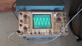
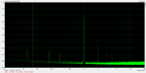
I was running it with a 400V supply with plate idling at 200V. The circuit is configured for a gain of 10. I ran the screen at 100V.
The scope capture is of the circuit putting out 200Vpk-pk. Unfortunately, I can't use the signal generator that I used for that to make a good distortion measurement as the generator puts out ~0.3% THD.
I drove it with 1.8Vrms from the sound card for the distortion measurement. Output was 18Vrms.
Attachments
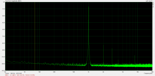
I'm pretty happy with this ADA4700 test setup. I'm getting a gain of 20 and pretty good output swing. This will be a great setup for trying driver stage ideas. Attached is a measurement of the soundcard looped-back so you can get an idea of how much (or little) distortion the ADA4700 is adding.
Attachments
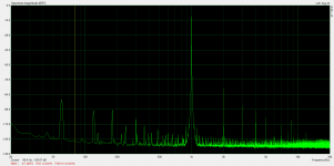
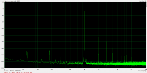
Now here are distortion results from the EL34. Output levels are 30Vrms, 75Vrms, and 105Vrms.
I couldn't go over 105Vrms with the 420V supply that the EL34 is currently hooked up to. Next I will have to construct an 800-1000V supply to test with.
I couldn't go over 105Vrms with the 420V supply that the EL34 is currently hooked up to. Next I will have to construct an 800-1000V supply to test with.
Attachments
Nice results! How did you configure the ADA4700? Inverter with gain of 20?
I did non-inverting with gain of 20. Feedback resistor of 100k. It seems to be a nice little op-amp. I bought some caps to put in parallel with the feedback resistor and try limit bandwidth and reduce distortion a bit. Haven't tried it yet, but I should be able to make it even better. There doesn't seem to be much high-order distortion there to suppress, which is nice.
Here is a picture of the op-amp. I bent the leads and flipped it upside down and made a heatsink out of a couple of pieces of wire for the thermal pad.
Attachments
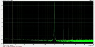
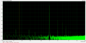
Well, I think I have a good signal generator amplifier for further experiment on this circuit idea. I added some filtering to the ADA4700 to limit bandwidth and suppress distortion a bit.
Attached is the distortion spectrum. Anything above 3rd harmonic is unmeasurable and distortion is <.01% all of the way up to the +-48V rails. This should be adequate for generating drive voltages to drive the EL34 all of the way up to where I want to test.
Next step is to construct the higher voltage B+ for further experiments with the EL34.
Note: the ~8.7k peak is some artifact of my measurement setup and is always present even without signal.
Attachments

Last edited:
- Status
- Not open for further replies.
- Home
- Amplifiers
- Tubes / Valves
- Idea for driver for CF output stage