I think i answered my own question, i have been testing the amplifier with RMAA and seeing identical gain and measurements on both channels with the gyrators set to 3ma, and the bias voltages the same. Plates were reading 123v & 116v.
Ale if your reading this i need help, i think i have damaged one of my Gyrator boards.
I had both set to 3ma (measured across the 10ohm resistor R5), i went back to tweak it and one channel read 8ma. Didn't understand why so i quickly wound the adjustment down to 3ma again, and now i am seeing 75v on the plate which makes no sense. Double checked the bias & filament voltages are correct, and tested the tube which is fine.
Any idea what is going on? I suspect i may have damaged the BF862 in J2?
Anode voltage and bias voltage determines operating point (Ua, Ia at -Vg) ... at specified tube and at given condition.
If the tube changing (another tube, or aging), the operating point also changing.
There are no two identical operating point of two tubes, but if it not too far -relative to each other-, it's irrelevant.
The important thing is tubes gain -preferably- similarity at near operating points.
Do you prioritize matching gain over similarity in THD spectra or try to get similar THD spectra and then adjust the gain elsewhere, for example, at the voltage divider just before the SF?
Thanks . nash
Theory question: I am using Ales Gyrator boards and Coleman filament regulators with cathode bias. What is more important to match, bias voltage or plate voltage?
With preamps, where the output swing is only a few volts, the DC Anode voltage needs only to be in the right range to yield a suitable bias level. So this is least important for tight control. The triode gm varies with anode current, and this is more relevant for good performance. So I would say aim for a matched anode current - and you can adjust the anode voltage and/or the bias voltage to get there, so long as they don't end up being wildly different.
Do you prioritize matching gain over similarity in THD spectra or try to get similar THD spectra and then adjust the gain elsewhere
If you measured enough large batch of -nearly- thousand years old tubes, you will realise, that selecting two "identical" tube is a real nightmare, it's almost "Mission Impossible".
")
The traders/vendors measuring "pairs" with tube testers.
The average -good- tube tester measures tube at given operating point where gm near -or not so near- to datasheet's value in this point.
I shows, that in this point (changing from one tester to another, no "fix" point of this tube) the tube condition near to required value or not ("good"-"not good", "%" etc.).
It says nothing from distortions, which is a function of given curves (Ua-Ia at given -Vg) to relative datasheet curves.
If you a lucky, and own a curve tracer (uTracer, eTracer etc.) which shows curves, you can compare curves from tube to tube, relative to datasheet's curves.
It' a "real" pairing, but slow, labour-intensive, costly (do you have few bunch of hundred years old tubes?).
Instead of this, the gm measuring at given operating point is accepted.
After this you can do THD spectrum analysis, but I say in advance that you will not two "identical" spectra, even measuring tight "pairs".
BTW some years ago I measured a few bunch of 801/801a tubes.
The difference of THD spectra was larger (better-worse), than measuring -good, but not excellent- 801a/VT-62 tube versus 25/VT-25!
Are the ST style 01A tubes thoriated
As I understand the UX201A and its variants like the CX301A had the thoriated tungsten filaments. In 1932 the ST style was adopted and the tube renamed 01A. Some of the documentation I have seen mentions the use of oxide coated filaments being used in the ST style tubes.
I have in my possession a supposedly NIB Sylvania 01A ST tube and it has the silvery getter on most of the tube. Does this mean it is thoriated? Are the oxide ones completely clear?
Any preference sound wise between the UX and the ST tubes?
Thanks. nash
There is no correlation between filament type and precipitated getter.
The thoriated tungsten filament is recognizable immediately, because it's glowing brightly (higher temperature).
See it in Thomas's page:
VinylSavor: 01A
VinylSavor: Tube of the Month : The UX201A
The thoriated tungsten filament is recognizable immediately, because it's glowing brightly (higher temperature).
See it in Thomas's page:
VinylSavor: 01A
VinylSavor: Tube of the Month : The UX201A
There is no correlation between filament type and precipitated getter.
The thoriated tungsten filament is recognizable immediately, because it's glowing brightly (higher temperature).
See it in Thomas's page:
VinylSavor: 01A
VinylSavor: Tube of the Month : The UX201A
Should the thoriated coated filament appear brighter than the oxide coated one?
I have gone thru Thomas' blog several times and while he has pictured the Sylvania ST 01A and other ST tubes he makes no mention of their filament coatings being different.
nash
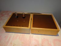
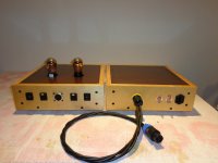
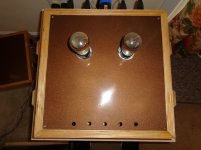
Two box 01A build
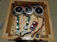
I finally completed my two box 01A build based on Ale Moglia’s low gain 01A which includes a voltage divider and source follower. The output feeds my Slagle AVC for volume control.
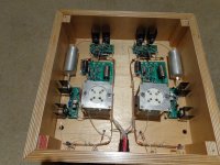
The PSU box contains two raw DC supplies for the filaments on Rod Coleman boards and the B+ is on the red Pete Millett board that has a Tent Labs MEC50 electronic choke. Four microphone cables form the umbilical. There are two switches wired in series, the first turns on the filaments and the second the B+; second one will not turn on unless the first is on. The tube towers have isolator blocks on them to control microphony. I used separate grounds for the L and R channels tied at the 0v HV in the PSU box. All wiring in the preamp box is 22awg silver except the short input/output wiring which is 24awg. Gyrator and source follower boards have 47uf electro’s // with 100nf stacked film caps for decoupling.
THD at 1v out is about 0.011% and doubles to 0.022% at 2v out. Gain is 4 with 100k/100k dividers; a difference of about 0.3db between the tubes at roughly similar operating points which I evened by padding the dividers.
The sound is excellent; detailed and well balanced with no harshness and the right amount of body and weight. I was surprised how well it does with large scale orchestral work. Superb image rendering of instruments at the rear of orchestra. Great dynamics. Zero hum and noise with ear to tweeter with my 93db OBL15’s at loud listening levels rising to a faint rush at full volume.
My sincere thanks to Ale Moglia and Rod Coleman and all those here who have inspired and helped me to build this preamp. I am very glad that I did.
Comments and suggestions would be appreciated.
nash
I finally completed my two box 01A build based on Ale Moglia’s low gain 01A which includes a voltage divider and source follower. The output feeds my Slagle AVC for volume control.
The PSU box contains two raw DC supplies for the filaments on Rod Coleman boards and the B+ is on the red Pete Millett board that has a Tent Labs MEC50 electronic choke. Four microphone cables form the umbilical. There are two switches wired in series, the first turns on the filaments and the second the B+; second one will not turn on unless the first is on. The tube towers have isolator blocks on them to control microphony. I used separate grounds for the L and R channels tied at the 0v HV in the PSU box. All wiring in the preamp box is 22awg silver except the short input/output wiring which is 24awg. Gyrator and source follower boards have 47uf electro’s // with 100nf stacked film caps for decoupling.
THD at 1v out is about 0.011% and doubles to 0.022% at 2v out. Gain is 4 with 100k/100k dividers; a difference of about 0.3db between the tubes at roughly similar operating points which I evened by padding the dividers.
The sound is excellent; detailed and well balanced with no harshness and the right amount of body and weight. I was surprised how well it does with large scale orchestral work. Superb image rendering of instruments at the rear of orchestra. Great dynamics. Zero hum and noise with ear to tweeter with my 93db OBL15’s at loud listening levels rising to a faint rush at full volume.
My sincere thanks to Ale Moglia and Rod Coleman and all those here who have inspired and helped me to build this preamp. I am very glad that I did.
Comments and suggestions would be appreciated.
nash
Attachments
Thanks PRR.
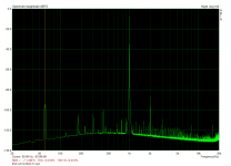
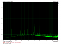
Andy, that small black box is the TentLabs MEC50 electronic choke. Works very well, I think. Just for a test I replaced it with a 100r resistor and saw the noise go up quite a bit on the spectrum analysis. I specifically reached out to Pete Millett and asked whether it would work well with Ale's gyrator and he replied that he thought it would.
nash
It's been a long time since I built my Dave Slagle AVC. Do you know what Dave says the source impedance should be under, for it to perform at its best?
If I remember you are going directly from the gyrator to the AVC? Ale's SF boards significantly reduce output impedance compared to gyrator output impedance. I measure about 400r output impedance with the SF at 1khz using 100k/100k divider.
nash
If I remember you are going directly from the gyrator to the AVC? Ale's SF boards significantly reduce output impedance compared to gyrator output impedance. I measure about 400r output impedance with the SF at 1khz using 100k/100k divider.
nash
I don't remember but Dave did change the gap a little on mine so it wouldn't saturate from too much gain. The 01A mu is 8 so even something like a 6N6P might saturate the AVC. Max voltage on AVCs are usually about 8-10v.
I did do some plots based on several different caps before the AVC.
I think the AVC likes higher source impedance, the output impedance varies on volume setting but typically in the 600-1000ohm range unless its cranked up.
The AVC is connected to the Gyrator and not using any kind of buffer. I wouldn't change a thing, its the best pre-amp I've had in 40yrs.
@Nashbap nice build, these 01a tubes make a really great preamp 
I didn't bother with the buffer either as i didn't think i needed it driving an F4, just used the output from the Gyrator direct. I also have salas shunt regulators before the gyrators boards which is probably overkill, but the end result is fantastic so i wont be changing it in a hurry
I didn't bother with the buffer either as i didn't think i needed it driving an F4, just used the output from the Gyrator direct. I also have salas shunt regulators before the gyrators boards which is probably overkill, but the end result is fantastic so i wont be changing it in a hurry
- Home
- Amplifiers
- Tubes / Valves
- 01A question