400R is more than enough to drive AVC.
I use higher impedance (cascode CCS low impedance output) in my #26 preamp (feeding through Salas SSHV regulator) to drive 400H TVC (S&B TX102), with correct operation.
Isnt lower input impedance the better for driving AVC's?
Thanks. nash
It's depends on the value of inductance.
If I remember correctly Dave's AVC has lower overall inductance than S&B primary, but it's impedance in the lower side is much greater than your output impedance.
If I remember correctly Dave's AVC has lower overall inductance than S&B primary, but it's impedance in the lower side is much greater than your output impedance.
I've been using my 01a preamp for a while now - pretty much exactly as per Ale's design, with a regular stepped pot on the input for volume control and I've been very happy with it. By a considerable distance the best sounding preamp I have built and my first DHT. I don't have a problem with noise, but I'm curious about the options to put the pot at the output of the circuit rather than the input. Is either one sonically better? I take it you would want a high value pot (>100k) at the output if you were implementing this?
The -good designed- benefit of active preamp is the low output impedance .. as low as possible.
This is the basis of connecting preamp to power amp via interconnect.
If the preamp output impedance is enough low, the difference in pronunciation due to the imperfection of interconnect can be minimized.
So in my opinion in this case the volume control would be at the preamp input (when the grid leak resistor anyway has large value).
Hi Euro 21
OT question pls. As 01a's are all old what if we are unable to have closely match them, can there be a way to adjust bias like output power tubes ?
Thks
OT question pls. As 01a's are all old what if we are unable to have closely match them, can there be a way to adjust bias like output power tubes ?
Thks
The -good designed- benefit of active preamp is the low output impedance .. as low as possible.
This is the basis of connecting preamp to power amp via interconnect.
If the preamp output impedance is enough low, the difference in pronunciation due to the imperfection of interconnect can be minimized.
So in my opinion in this case the volume control would be at the preamp input (when the grid leak resistor anyway has large value).
However, in the case of an AVC the output impedance at most attenuation levels is very low so it would make sense by the same logic to place it after the preamp unlike the resistive version volume control before the preamp as suggested.
Another question that I couldn't quite figure out as I read through this thread. The newer ST type 01a tubes - do these sound better/worse etc than the older types with silvered balloon shaped glass? I appreciate the older ones are more fragile etc but leaving that aside....
It's depends on the value of inductance.
If I remember correctly Dave's AVC has lower overall inductance than S&B primary, but it's impedance in the lower side is much greater than your output impedance.
Dave's AVC can be stack modified for inductance.
Thank you. I am re acquainting myself with the AVC having built it a while back in 2015.
nash
The -good designed- benefit of active preamp is the low output impedance .. as low as possible.
This is the basis of connecting preamp to power amp via interconnect.
If the preamp output impedance is enough low, the difference in pronunciation due to the imperfection of interconnect can be minimized.
So in my opinion in this case the volume control would be at the preamp input (when the grid leak resistor anyway has large value).
This preamp either needs some really good cables (low capacitance) or the impedance needs to be lowered by a buffer or AVC.
This is what it could look like with various cables without the AVC at output.

The Globes did it for me but don't perform as well on paper. They can be noisy and difficult to find a good pair.Another question that I couldn't quite figure out as I read through this thread. The newer ST type 01a tubes - do these sound better/worse etc than the older types with silvered balloon shaped glass? I appreciate the older ones are more fragile etc but leaving that aside....
Hi Euro 21
OT question pls. As 01a's are all old what if we are unable to have closely match them, can there be a way to adjust bias like output power tubes ?
Thks
I used a HV maida supply to tweak mine, you can also adjust it at the Gyrator.
Last edited:
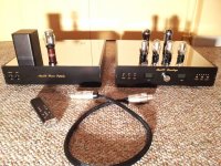
I actually use the Bent Audio TAP-X remote controlled passive preamp "wrapped around" my 01A tube preamp. The Bent has at its heart a Slagle nickle core, silver-wound AVC, on the output of the 01A. I couple the tube to the AVC using a lossy parafeed arrangement, which allows me to achieve excellent low and high frequency bandwidth throughout the volume control range. Since I had some room in the chassis I also built in a Buffalo IIISE Sabre DAC so now the unit is also an 01A output DAC. A relay allows me to switch between DAC and other preamp functions.
Sound is excellent!
BTW, I prefer the sound of the balloon tubes as well, with RCA UX-201A being my favorite. I originally built it as a 26 preamp, but switched over to 01A recently. I prefer the 01A.
Sound is excellent!
BTW, I prefer the sound of the balloon tubes as well, with RCA UX-201A being my favorite. I originally built it as a 26 preamp, but switched over to 01A recently. I prefer the 01A.
Attachments
Last edited:
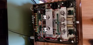
As usual, that's some nice looking work you did there. Can you share the parafeed arrangement you did.
Hi Euro 21
OT question pls. As 01a's are all old what if we are unable to have closely match them, can there be a way to adjust bias like output power tubes ?
Thks
Adjust the filament power.
As usual, that's some nice looking work you did there. Can you share the parafeed arrangement you did.
The AVC was configured in a 3x3 stack for ~150H inductance. The AVC is fed from the mu output of a K&K Audio compact cascode CCS on top of the 01A.
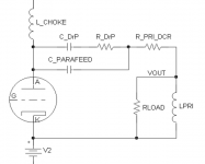
I used lossy parafeed (aka Damped Resonance Parafeed or DrP) with a 1uF cap, and in parallel an additional 3.3uF DrP cap with an 8080ohm resistor in series with it. This arrangement smooths out the peaking at low frequencies and extends the -3dB point down to 4.8Hz.
It's a neat trick because you can use a very high quality small cap (in this case a 1uF Duelund CAST Copper) through which almost all the signal passes and a lesser quality large cap (in this case a 3.3uF Mundorf Supreme) to augment in the bass region.
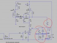
Like this, but instead of the choke load there is a CCS mu output and the cathode is connected to ground and the grid is battery biased.
Attachments
Last edited:
Magz,
Thanks for posting this. What Hz were you experiencing the resonant peak at and how high a db was it?
I am finding a peak around 25hz which is about 7db higher. I have gone thru the Intact Audio Forum and see that you posted this solution there. Dave Slagle has also pointed out that a bit of a resonant peak combats the natural rolloff of speakers. Honestly, I cannot hear any extra loudness in the bass.
How did you determine the values for the caps and resistor. With this circuit do you eliminate the cap to G normally found after the output cap which in Ale's schematic is shown at 510K?
Notice you too are in NJ. I am south of Philly.
nash
Hi magz, nashbap
If you're looking for a compact reference on designing for that resonance, Frank's electron tube data has a copy of Terman's 1943 Radio Engineer's Handbook here: electron Tube Data sheets - No brand related documents
Beginning on page 371 there is a discussion of "Miscellaneous Coupling Systems for Audio-frequency Voltage Amplifiers". The discussion of "Transformer Coupling with Shunt (Parallel) Feed" begins at the bottom of that page, with relevant graphs at Figure 14 (b) on page 374 illustrating the effect of altering the value of the coupling or "parafeed" capacitor.
Enjoy 🙂
Magz,
Thanks for posting this. What Hz were you experiencing the resonant peak at and how high a db was it?
I am finding a peak around 25hz which is about 7db higher. I have gone thru the Intact Audio Forum and see that you posted this solution there. Dave Slagle has also pointed out that a bit of a resonant peak combats the natural rolloff of speakers. Honestly, I cannot hear any extra loudness in the bass.
How did you determine the values for the caps and resistor. With this circuit do you eliminate the cap to G normally found after the output cap which in Ale's schematic is shown at 510K?
Notice you too are in NJ. I am south of Philly.
nash
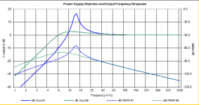
I have a neat little Excel spreadsheet posted online about a decade ago by a guy named VoltSecond that allows one to calculate the proper cap and resistor values and shows the resulting frequency response and PSRR for two different designs at a time.
I don't see a way to attach a .xls file on this post or I would do that. Instead I attach a screenshot of the graphs showing the peaking with just the 1uF cap (design 1 in blue) and with the 1uF and 3.3uf-8080R in parallel (design 2 in green). It's clear how design 2 minimizes the extreme peaking while still leaving a bit of bass boost in the lower frequencies. I have verified this behavior with measurements.
Attachments
- Home
- Amplifiers
- Tubes / Valves
- 01A question