Switched out the biasing resistors for the SiC boards during the week.
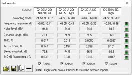
As expected it did clean things up a bit, measured results where a little surprising to be honest, and bordering on the limits of my test setup for frequency response and noise floor. I just wish a had measured the harmonic content before and after as i believe that would have been far more telling.
Musically, there is a noticeable improvement in clarity, dare i say the old setup was a tad smoother and more romantic sounding, i suspect there was more harmonic content in there making it a little more warm and cuddly.
I can absolutely see why someone would prefer it that way, and i will admit i wasn't immediately sold on them, it took a few days of listening to come to the conclusion that the SiCs are right, and that they are staying. I will be using this amplifier for everything, Music, Vinyl, TV, Netflix, Youtube videos you name it so the cleaner option is the better choice for me.
Still deeply impressed with this pre amp, you know you are onto something good when you cant stop feeding music through it 😀
Attachments

Glad you like it. The SiC bias arrangement was a great thing to land on. I’m very happy abs haven’t found anything to sound better on the cathode of this preamp. Who knows, we may find it In The future!
Ale
Ale
Switched out the biasing resistors for the SiC boards during the week. Dare i say the old setup was a tad smoother and more romantic sounding, i suspect there was more harmonic content in there making it a little more warm and cuddly. I can absolutely see why someone would prefer it that way.
How flattering - that's me! Romantic, smooth, warm and cuddly. I always knew it.
I'm back on filament bias. For me smooth does it. My 01A stage is driving my EL12n outputs in my current main amp.
Glad you like it. The SiC bias arrangement was a great thing to land on. I’m very happy abs haven’t found anything to sound better on the cathode of this preamp. Who knows, we may find it In The future!
Ale
Some active circuitry perhaps? I experimented with biasing a small preamp tube using LEDs, and a TL431 shunt regulator. The circuit had a lot better high frequency response with the 431 vs the LED, but the regulator itself is inherently very noisy which created an audible hiss on the audio output. There is something there though worth exploring...
How flattering - that's me! Romantic, smooth, warm and cuddly. I always knew it.
I'm back on filament bias. For me smooth does it. My 01A stage is driving my EL12n outputs in my current main amp.
🙂 ...filament bias seems to sounds much better to me too.
What device would you recommend to use for source follower? What mosfet? IXTP or something else?
Thanks
Thanks
Quoting Ale from his blog
"Hi Tomislav,
I use the STF3LN80K5 which has a plastic package which can be bolted directly on the chassis, protection diodes between G and S and more importantly very low Crss (0.1pF):
https://www.st.com/resource/en/datasheet/stf3ln80k5.pdf
You can’t ask for more!"
"Hi Tomislav,
I use the STF3LN80K5 which has a plastic package which can be bolted directly on the chassis, protection diodes between G and S and more importantly very low Crss (0.1pF):
https://www.st.com/resource/en/datasheet/stf3ln80k5.pdf
You can’t ask for more!"
Indeed, thanks Nash for sharing. Cheap and excellent MOSFET for the job. Also as a plus it comes with protection diodes inside the dye which reduces the overall part count for the follower
Btw, for the ones who love the DHT sound and want a low gain stage due to their systems requirements, here is a good example to look into. I love the sound of the 01a stage:
01a Low Gain DHT preamp (finished) – Bartola(R) Valves
You can implement effectively any medium mu DHT with low current and high rp, whilst driving successfully any low impedance amp (eg solid state for example)
Cheers
Ale
Ale, I suppose there is no issue changing the value of R3 in the divider to get an output gain of ones choice keeping R2 at 100k. For example, R3 at 100k should yield gain of 9db, roughly half of the otherwise 18db.
Thanks. nash
Thanks. nash
Yes, the higher R3 the better to provide signal headroom to the Source Follower as the circuit is DC-coupled and we are looking to avoid extra complexity.
If R3 is lower, there is a way to make it work by adding a PMOS to uplift the tail of R3 to get a higher DC level to allow the SF to operate well when swinging larger volts. However, is worth looking at this in detail as may not be needed if we are using the stage as buffer or pre-amp of the common signal levels (e.g. 2V).
Other than that, I think is a great solution for using a DHT and provide a low gain stage with a great performing (and sounding) stage which is a mu-follower. A similar approach is taken with a SUT at the input and then a step down transformer as anode load. This way you can get the best out of the DHT stage whilst reducing the impact of the microphonic noise etc. This is something I discussed with my friend DHTRob who led me this path and played with the UX-120, which is a lovely sounding valve but greatly microphonic.
Enjoy it as much as I do!
Cheers
Ale
The STF3LN80K5 MOSFET is indeed a great MOSFET for a tube driver stage. It’s a great MOSFET for a concertina too, as many people don’t know yet.
Regards, Gerrit
Regards, Gerrit
Hello Everyone,
I have decided to take the plunge into tubes and build a 01A preamp using Ale's Gyrator and Rod Coleman regs. Would appreciate advice on a few questions:
1)I plan on using one B+ supply to feed both channels with no Salas SSHV2 regs. I also plan on utilizing the B+ supply for powering the Source Follower as outlined in Ale's low gain 01A version 6 schematic. What ma draw should I plan for? If the SF is CCS biased at 10ma and the tube around 5 ma can one assume that the total draw for each channel is under 20ma, considering some losses here and there?
2)Given that I plan on building the PSU in a separate box with a 1 meter umbilical to the amp do I need to use a decoupling cap for the B+ at the entry to the gyrator or at the SF? And if so what value?
3)It looks like most recommend the Russian FT3 0.22uf for the output cap? What brand seems to work best for the gyrator cap?
4)Any suppliers of CX301A that folks are happy with? Do I look for tubes that are claimed to have been matched on the tube tester?
Thanks.
nash
3) Depends on the input impedance of your amplifier. Into a 47k load i settled on .47uf in my build to get the desired low frequency response. Have a play here and see what works for your application RC High-pass Filter Design Tool
I used a K72P Russian Teflon capacitor for the .47uf, and a .1uf FT-2 on the Gyrator board.
4) My advice, buy the cheapest set you can find for building and testing. They are super fragile, i have had a bunch of them die with broken filaments when shipping, and had a couple let go after repeated power on/off's while testing. When you have it all dialled, buy a nice set of matched tubes.
1)
Yes, using one B+ is good solution..... if you use CCS or "gyrator" as 01a anode load. These are high PSRR devices.
Else you must to use complex PSU with low ripple and hum.
SF and CCS or gyrator loaded VAS stage practically independent of the B+ voltage (if it as great as B+= anode voltage + swing peek + 30...40V).
2.)
I use there 47uF // 100nF.
3)
I use in these devices teflon FT3 // V-Cap or V-Cap or Duelund.
The order of quality is the same ... but price expands to the sky. :-(
hi Nash, Any transistor follower (valve follower too, I suspect) needs good supply decoupling.
The decoupling should be right on the drain of the FET, for best control of oscillation risk. The idea is to prevent any part of the supply wiring from thinking about looking inductive enough to form a resonance with stray capacitance.
With FETs, the oscillations can reach 10MHz or more, so a stacked-construction film capacitor is worth seeking out - these have low inductance. 100nF - 220nF.
Add an electrolytic 47-100µF.
Thank you Mark, Bela and Rod for your suggestions.
I took a another look at Ale's 01A version 6. I missed seeing the decoupling caps C1 and C2. My apologies. Rod, I found one stacked film cap thru a Mouser search. Is this appropriate, in // with an electrolyte as suggested?
F612JQ104K250C KEMET | Mouser
Regarding the B+ supply, I was thinking of using this PCB with a MEC. The MEC50 is good for 50ma while the MEC100 for 100ma; which is why I inquired about the maximum current draw from the B+ supply.
MEC Power SUpply
Has anyone used these? Any thoughts?
nash
Theory question: I am using Ales Gyrator boards and Coleman filament regulators with cathode bias. What is more important to match, bias voltage or plate voltage?
Anode voltage and bias voltage determines operating point (Ua, Ia at -Vg) ... at specified tube and at given condition.
If the tube changing (another tube, or aging), the operating point also changing.
There are no two identical operating point of two tubes, but if it not too far -relative to each other-, it's irrelevant.
The important thing is tubes gain -preferably- similarity at near operating points.
If the tube changing (another tube, or aging), the operating point also changing.
There are no two identical operating point of two tubes, but if it not too far -relative to each other-, it's irrelevant.
The important thing is tubes gain -preferably- similarity at near operating points.
- Home
- Amplifiers
- Tubes / Valves
- 01A question