Steve,
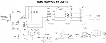
you just need to use half of the schematic in post 1.
If you wish i can draw the schematic for you.
For the potmeter you can use lin or log type and any resistance.
So quad potmeters are possible.
Ronny
That would be grand! Yes, please, and especially mark that part of the circuit that is the 'volume control' doubled potentiometer itself.
@Anatech: what is a turnkey solution? Are you suggesting I need resistors between my high-voltage supply (a step-up converter) and my nixie?
Regards,
Steve Satak
Hi Steve,
Without some limiting resistance, the tube elements would "strike" and you would have excessive current flow. Bad for tube, bad for driver IC. So just like a neon lamp, you need to put some resistance in series with the display tube anode. A seven segment display needs resistance in series with each segment as more than one is lit at any time.
The term "strike" is used to describe the resistance of the gas in the tube breaking down, initiating electron flow which quickly turns into a full fledged arc. That destroys things. The difference between an arc and normal electron flow is how much current is allowed to flow. That is controlled by how much resistance is in series with the tube. A numeric tube has fully formed numbers, so only one element is lit at any one time. You can use one resistor in series with the anode (to your HV supply). If you want to use a seven segment display, the numerals are made up of segments. You need to light combinations of segments to form the numeral. For these you would need a resistor in series with each cathode in order to equalize the brightness of the segments (and the entire formed numeral). The numeric tubes look way better than the seven segment type displays.
A "turnkey" solution basically means that everything you need is in the chip and the applications information printed on the data sheet (unless you get abbreviated data sheets missing most of the information). It wouldn't hurt for you to look up information on the basic display type. Also read up on neon lamps as it is the same principle. After that you'll know more than enough to confidently design these types of displays. Learning about things like this is fun.
-Chris
I will be using an IN-4.
I am sure you are right - hunting this down will teach me about such things. But I am new to neon and to be honest, don't have much time to gen up a circuit so I can get the parts and do a proof-of-concept demonstrator. The nixie display will run $30 each and I need to justify that cost x 10.
Regards,
Steve
Something like this page? Quite a lot of info in here, although I have not had time to make heads or tails of it.
https://threeneurons.wordpress.com/nixie-power-supply/
I have been using a current-limiting resistor formula for LEDs for a couple of decades, so this is nothing new. But the forumula found on this blog seems needlessly baroque. Or maybe I just need to read it further?
Regards,
Cent13
https://threeneurons.wordpress.com/nixie-power-supply/
I have been using a current-limiting resistor formula for LEDs for a couple of decades, so this is nothing new. But the forumula found on this blog seems needlessly baroque. Or maybe I just need to read it further?
Regards,
Cent13
There are no stupic questions.
And yes the pot who indicates the position of the volume pot is connected as sensor. You can use also other value for sensor pot, like 22k, 47k or 100k. If you need 47k for stereo volume controll, you can use 47k quad potmeter.
With the 47k trimmer you can adjust zero position ( display 00 )And with the 10k pot you can adjust max position( display 99).
Ronny
Last edited:
")
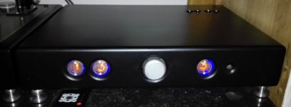
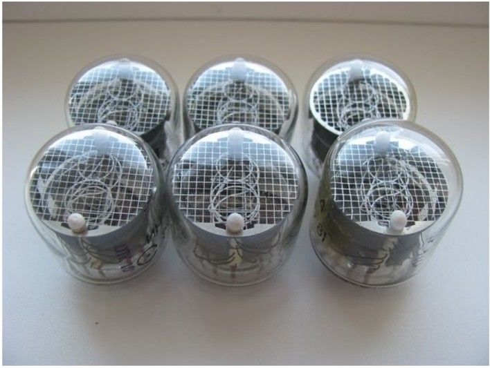
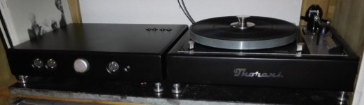
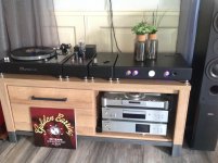
Full glow.
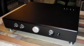
Beautiful...what are those tubes projecting out of the top cover
towards the back ?
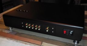
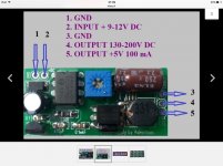
What is the DC-DC converter you are using for the Nixies - it may
be good to provide pins on the PCB for one of the tayloredge modules
http://www.tayloredge.com/storefront/SmartNixie/PSU/comparison.html
That are 6n16 tubes from the tube phono stage.
http://www.diyaudio.com/forums/analogue-source/242855-mini-me-phono-preamp.html
The nixie power supply comes from Valentinas on ebay.
POWER SUPPLY in14 in16 in18 in12 nixie tube Adjust Voltage DC 130-200V | eBay
http://www.diyaudio.com/forums/analogue-source/242855-mini-me-phono-preamp.html
The nixie power supply comes from Valentinas on ebay.
POWER SUPPLY in14 in16 in18 in12 nixie tube Adjust Voltage DC 130-200V | eBay
Attachments
Last edited:
- Home
- Amplifiers
- Tubes / Valves
- Retro nixie volume indicator