Member
Joined 2009
Paid Member
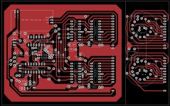
Today made the pcb design. I shall test it next week.
nice layout!
I hope not.
Distance to signalcables is 10cm but i will test it if there is any influence.
Ronny
Distance to signalcables is 10cm but i will test it if there is any influence.
Ronny
video of my arduino remote control talk for burning amp 2015 is up. there's a section in the talk where I show my wireless nixie 'clock' that also shows the dB volume level from my relay attenuator.
enjoy 😉
https://www.youtube.com/watch?v=7fvRZYyTh90
enjoy 😉
https://www.youtube.com/watch?v=7fvRZYyTh90

linuxworks,
When is your website Sercona Audio going to be done?
its quite out of date, but I have not had time to really update it properly. I have over 5 separate remote-control a/v projects going at once and its a bit of a juggle to get anything done with that much context-switching 😉
I'm trying to get a series of things all working as a system before I go to the green-board stage. and since its a whole system, its taking longer to get everything worked out to where I would feel comfortable committing to pcb's and firmware features.
thanks for the interest. I will definitely post on the appropriate forums when I have some first-version boards and will look for beta-testers on the first run of boards.
Last two weeks i had time to build and test the PCB. But it had a fault around the 74LS04 IC. After solving the problem i decided to make a new PCB . This pcb i will test next week.
Attachments

Last edited:
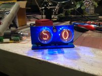
This evening completed the second tryout and it works.
See on youtube:
https://youtu.be/FfgYGh3b0X0
Pcb and schematic as build will follow soon.
See on youtube:
https://youtu.be/FfgYGh3b0X0
Pcb and schematic as build will follow soon.
Attachments
I think a USB-programmable microcontroller would be a good solution for a future version of this project, because the circuit and the PCB would be much smaller and simpler.
And it would allow more possibilities. A few ideas:
- user-adjustable number of volume steps
- dynamic PWM Nixie luminosity control (the light dims down some time after you change the volume, to prolong the tube's life)
- cross-fading from one digit to another as you change the volume
- controlling RGB LEDs to have dynamic color backlighting (for example going from blue at zero volume to red at maximum)
- a countdown for filament heating time during startup...
- other ideas?
You can think of a lot of extra options when using a microcontroller.
For me just a volume display is enough. And designing and building this thing within a month is not possible for me when using a microcontroller. Then first i must learn the programming for the microcontroller and possible solder smd.
And using a switching supply is already a gamble because the preamp has also a phone preamp. A microcontroller is then a second source to worry about regarding HF radiation.
Last edited:
I am happy to share the source to my arduino clock and display.
the cool part is that its radio based (rf) so the display is not connected to the audio system at all, directly. any nixie noise or psu noise does not get into the audio system.
the audio system sends rf packets on each vol change to the display box that could be sitting in some other room, if you wanted. the beauty of wireless 😉
but yes, you do need a controller for this. with all the arduino sample code out there and cheap dev kits, you should think about getting into it. lots of community folks out there willing to help you get started; we all had to start somewhere.
You can think of a lot of extra options when using a microcontroller.
For me just a volume display is enough. And designing and building this thing within a month is not possible for me when using a microcontroller. Then first i must learn the programming for the microcontroller and possible solder smd.
And using a switching supply is already a gamble because the preamp has also a phone preamp. A microcontroller is then a second source to worry about regarding HF radiation.

Thanks Mooly.
Linuxworks, i already have used a arduino mega256 board to control a tube preamp. But my build in tube phono preamp did not like the presence of the microcontroller. And i did not like the combination of tubes and LCD display.
I like my tube amps as retro as possible with a little accent of luxury.
But please share your designs to inspire me and our fellow readers.
But my build in tube phono preamp did not like the presence of the microcontroller.
I am using Arduino in a tube line and phono preamp, where it does remote volume and channel control, and in a fixed bias tube power amp, where it monitors current through the tubes and cuts the PSU in case of bias faults.
They work flawlessly, no trace of injected noise in my builds. So people shoudn't be afraid of microcontrollers.
http://www.diyaudio.com/forums/anal...d-ldr-volume-source-selection-controller.html
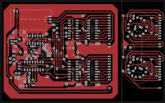
PCB
Bottleful idea and I would love to build one for myself. Is it any way to get PCB design in Graber format. I have very positive experience with DirtyPCB.com and if it is inside of 10cm by 10cm then it will be $24 with the shipment for 10-12 PCBs. Please let me know.
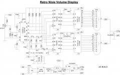
As Build.
Bottleful idea and I would love to build one for myself. Is it any way to get PCB design in Graber format. I have very positive experience with DirtyPCB.com and if it is inside of 10cm by 10cm then it will be $24 with the shipment for 10-12 PCBs. Please let me know.
Am doing this, but on a smaller scale...
Say, I have to come up with a single-digit nixie volume display for a project we're working on.
It's going to be a steampunk set of powered speakers. So far I have the tube pre-amp, the speakers and their amp, and the prospective casing.
What I don't have is a nixie volume indicator.
What I propose to do is this:
Using a ganged pair of potentiometers, the first pot will control the gain on the pre-amp board. The second pot will control the voltage input to a CA3162, which will feed the resulting level in BCD format to a 74141 nixie driver, which will drive a IN-4 tube.
Easy to write, but I have no idea what sort of supporting circuitry this will require. It seems simple, but the CA3162 will need supporting discrete components even though it is only driving a single display tube.
Any suggestions? I will gladly pay for a working design via PayPal: I have to make ten of these things by Christmas of 2016.
Regards,
Steve Satak
(Cent13)
Hi gideon1990,
Koifarm did this the exact correct way. I would have used the CA3162 and the high voltage driver. Your ICL7107 would have lasted until you turned the power on - poof! To use your choice of IC, you would have needed to put a high voltage buffer chip between it and the display. Since this project only needs 3 digits and doesn't go negative (-99 is the max for CA3162), the choice of chip was perfect!
Say, I have to come up with a single-digit nixie volume display for a project we're working on.
It's going to be a steampunk set of powered speakers. So far I have the tube pre-amp, the speakers and their amp, and the prospective casing.
What I don't have is a nixie volume indicator.
What I propose to do is this:
Using a ganged pair of potentiometers, the first pot will control the gain on the pre-amp board. The second pot will control the voltage input to a CA3162, which will feed the resulting level in BCD format to a 74141 nixie driver, which will drive a IN-4 tube.
Easy to write, but I have no idea what sort of supporting circuitry this will require. It seems simple, but the CA3162 will need supporting discrete components even though it is only driving a single display tube.
Any suggestions? I will gladly pay for a working design via PayPal: I have to make ten of these things by Christmas of 2016.
Regards,
Steve Satak
(Cent13)
Steve,
you just need to use half of the schematic in post 1.
If you wish i can draw the schematic for you.
For the potmeter you can use lin or log type and any resistance.
So quad potmeters are possible.
Ronny
you just need to use half of the schematic in post 1.
If you wish i can draw the schematic for you.
For the potmeter you can use lin or log type and any resistance.
So quad potmeters are possible.
Ronny
- Home
- Amplifiers
- Tubes / Valves
- Retro nixie volume indicator