I build the Nixie volume indicator From the "as build" schematic. Sadly no joy, multiple numbers light up at the same time and changing the sensor pot doesn't make a difference. I double checked the PCB I made and that seems ok. I think I got some bad 74141's. The inputs are switching between 0 and about 4,5 volts when changing the sensor pod, so that's ok, nothing happens with the outputs though. Tonight I will remove the 74ls75 and manual connect the inputs of the 74141 to ground and see what happens, but I've got the feeling I need to go hunting for new 74141's [emoji24].
Ronny, can I ask why you chose for 22k as anode resistor? It seems a bit high to me. Is it to preserve the Nixie life? I could be completely wrong of course but just learning and trying to understand.
And just in case, do you know where to buy the 74141 in Holland?
Ronny, can I ask why you chose for 22k as anode resistor? It seems a bit high to me. Is it to preserve the Nixie life? I could be completely wrong of course but just learning and trying to understand.
And just in case, do you know where to buy the 74141 in Holland?

So tonight I connected all 4 inputs of the 74141's to ground to make sure that they were low, that should result in a 0 displayed. That didn't work, Vcc is present, gnd is connected, so I guess the 74141's are really defective. Even with the 74ls75's removed multiple numbers are displayed. I removed the 74141's also and manually connected the output pins to ground, that works and shows the correct number corresponding to the output.
Found a seller of K155ID1 Nixie Drivers and ordered them, I hope that solves the problem. I really like this volume indicator and hope I will get it to work....
Found a seller of K155ID1 Nixie Drivers and ordered them, I hope that solves the problem. I really like this volume indicator and hope I will get it to work....
So replaced the 74141's with the new K155ID1's and everything works as it should now, nice work Ronnie, I like it a lot[emoji3], thank you!
Excellent project Ronnie!
I will definitely built this Volume indicator and add to my upcoming tube preamp kit project!
I have IN-1 tubes they are a little larger in diameter and require 200V (I think that's the only difference) All I will need to do is bump up voltage on DC/DC PS right?
Thank you!
I will definitely built this Volume indicator and add to my upcoming tube preamp kit project!
I have IN-1 tubes they are a little larger in diameter and require 200V (I think that's the only difference) All I will need to do is bump up voltage on DC/DC PS right?
Thank you!
Right.
200v is max for IN-1 tube.
I still use mine on a daily basis in my preamp. No problems at all.
200v is max for IN-1 tube.
I still use mine on a daily basis in my preamp. No problems at all.
Hello Ronny
-Two Years Later
😆
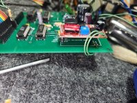
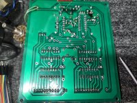
Looks like I made an OK PCB, collected all ICs, some caps was in allot higher voltage, but I could not spend any more $ and I want to see this working, so I used what I had (it's only 3 components) the rest as per your schematics.
Everything looks right, but displaying not working right, only one Nixie is displaying, and it's showing random numbers, sometimes multiple segments glow together.
When I adjust Sensor POT I do see, Nixie reacting, but it never stops, numbers continue to change, even if stop adjusting it
On CA3162 pin 8 and 9 - 47k "0" adjustment, also makes changes on the same nixie indicator, but again also random numbers
Second indicator does not light up, I did check the tube on bench PS with 10k resistor on anode, and it's glowing.
Anode viltage on small red eBay power-supply is 160VDC
All ICs are getting correct power
Do you know what can possibly cause this irrational behavior?
Thank you.

-Two Years Later
😆
Looks like I made an OK PCB, collected all ICs, some caps was in allot higher voltage, but I could not spend any more $ and I want to see this working, so I used what I had (it's only 3 components) the rest as per your schematics.
Everything looks right, but displaying not working right, only one Nixie is displaying, and it's showing random numbers, sometimes multiple segments glow together.
When I adjust Sensor POT I do see, Nixie reacting, but it never stops, numbers continue to change, even if stop adjusting it
On CA3162 pin 8 and 9 - 47k "0" adjustment, also makes changes on the same nixie indicator, but again also random numbers
Second indicator does not light up, I did check the tube on bench PS with 10k resistor on anode, and it's glowing.
Anode viltage on small red eBay power-supply is 160VDC
All ICs are getting correct power
Do you know what can possibly cause this irrational behavior?
Thank you.
Hello,
great to see you are building the display.
I can help you in a view steps to analyse were the problem is.
First i like to know were the green wires from the 170v adapter board are going to?
I have no wires there. 12v is supplied from the regulator.
great to see you are building the display.
I can help you in a view steps to analyse were the problem is.
First i like to know were the green wires from the 170v adapter board are going to?
I have no wires there. 12v is supplied from the regulator.
Thank you very much.
Yes, green wires are 12V for DC/DC PS.
Valentinas33 from eBay change the board a little since your original build, board is now wider and 170V pin is swapped with GND now, so caught that before making PCB, but board size, I think missed something in my calculations, so now I have ho;es on the red PCB not aligned with green PCB
Thank you.
Attachments
Lets start with checking the nixie driver IC, nixie and hv power supply. When appling a BCD code on the inputs of the nixie driver the correspondent number should light up. Look at the table below.
Remove the latch buffer 74ls75 before the nixie driver k155n out of their socket. Now you have access to the ABCD inputs to the nixie driver. Apply with four wires a code from the table. 0 = 0V and 1 = +5V. Please confirm that the right number lights up. Do that for both displays.
Sorry for delay. Work got in between, traveled out of state.
This afternoon dis some test, and results are strange (same results on both K155 ICs):

Nixie's are not wired correctly?
L - 0, H-5V
Thank you.
This afternoon dis some test, and results are strange (same results on both K155 ICs):
Nixie's are not wired correctly?
L - 0, H-5V
Thank you.
yes, rewire and do they burn good?Sorry for delay. Work got in between, traveled out of state.
This afternoon dis some test, and results are strange (same results on both K155 ICs):
View attachment 1102365
Nixie's are not wired correctly?
L - 0, H-5V
Thank you.
Yes, and remove counter CA3162 and puls trigger 74ls04. Now apply BCD code at the CA3162(pin 1,2,15,16) towards the latch buffer. When apply a 5V trigger on pin 10 and 12 from the 74ls04 socket the number on the display should change.
Sorry I was on vacation 🙂
Before I remove Counter and Trigger, I would like to tell you what's happening after I corrected pinout on nixie tube, and reinstalled Buffer back in the socket.
I was able to set 0 with 47ohm trimmer on Counter pin 9 and 8, and now when I turn "sensor" pot I get 0,1,2 and 3 but not smooth, it's like 0+1 glowing same time till halfway, than I have 1 for little wile, in between I get all 3 digits glowing, and at the end I have 3... Is it possible that my 47k sensor pod is bad? I don't see any other segments to glow other than 0,1,2 and 3 in weird order, and second nixie still dark again
- Home
- Amplifiers
- Tubes / Valves
- Retro nixie volume indicator