One more quick question, please. Does the 6L6 have less gain than the EL84 as the simulation suggests? I can't see anything about gain in the datasheet

Generally speaking, in a pentode, transconductance (gm) dictates gain.
6L6GC gm = 5.2mA/V (with Va = 350V, Vg2 = 250V, Vg1 = -18V)
EL84 gm = 11.2mA (with Va = 250V, Vg2 = 250V, Vg1 = -7.3V)
--
Hi
The soviet 1sh29b showes crossing plate curves in the area of the knees. See curves in my post #2097.
My goal is to find a GENERIC approach to mimic this phenomenon in spice.
To achieve that, I need further tubes showing this effect.
Does anybody know other tubes with crossing plate curves?
Thanks in advance,
Adrian
The soviet 1sh29b showes crossing plate curves in the area of the knees. See curves in my post #2097.
Attached an other version of the specification. I think this phenomenon can be seen from the plate curves, especially at Ug1 = -1,5 V.
Do you think that it is not "real" feature?
Also, isn't the Cg1_a < 0.005 pF ? (проходная)
Attachments
1sh29b model finished!
Hi artosalo
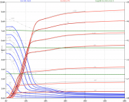
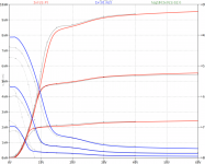
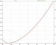
It took some time to get my 1sh29b spice model on a satisfying level - but now I'm happy with the result!
As in every development, there still remains some improvement potential, e.g. the Ig1 raise at very low Va is still not addressed. However, I'm sure my 1sh29b model is currently the best approach worldwide.
all the best, Adrian
Hi artosalo
It took some time to get my 1sh29b spice model on a satisfying level - but now I'm happy with the result!
As in every development, there still remains some improvement potential, e.g. the Ig1 raise at very low Va is still not addressed. However, I'm sure my 1sh29b model is currently the best approach worldwide
.all the best, Adrian
Code:
*1sh29b LTspice model based on the generic tetrode/pentode model from Adrian Immler, version4, Nov. 2019
*Important assumptions: both heaters are in parallel, heater- = GND, g3 is connected to GND
*A version log is at the end of this file
*Params fitted to measured data from a sample by Adrian Immler, Nov. 2019
*fit graphs see [URL="https://www.diyaudio.com/forums/tubes-valves/243950-vacuum-tube-spice-models-213.html"]Vacuum Tube SPICE Models[/URL]
*This model is an enhancement of Adrians generic triode model to achieve tetrode/pentode behaviour.
*Hence, it is also suitable when the tetrode/pentode is "triode connected".
*Convenient for tetrodes, power beam tetrodes and g3-grounded pentodes.
*Copes secondary emission effect!
*
*                 plate (in this model, "anode" means the internal virtual triode anode)
*                 | grid2
*                 | |  grid1
*                 | |  |  cathode
*                 | |  |  |
.subckt 1sh29b_i4 P G2 G1 K
.params
*Parameters for the space charge current @ Vg <= 0
+ mu1 = 12      ;Determines the voltage gain @ constant Ia
+ ks = 1k20     ;Permeance factor. Has to be readjusted if xs is changed
+ Vg0 = -0.75   ;Offsets the Ia-traces on the Va axis. Electrode material's contact potential
+ kp = 37       ;Mimics the island effect
+ xs = 1.68     ;Determines the curve of the Ia traces. Typically between 1.2 and 1.8
*
*Parameters for an optional space charge current reduction @ Vg > 0
+ kIsr = 0.16   ;Va independable Is reduction, a function of Vg1
+ Rg1i = 100    ;Internal grid1 resistor which causes an extra Is drop when Va approaches zero.
*
*Parameters for assigning the space charge current to Ia and Ig @ Vg > 0 and small Va
+ kB1 = 0.3     ;Describes how fast Ia_virtual drops to zero when Va_virtual approaches zero.
+ radl = 500    ;Differential resistance for the Ia emission limit @ very small Va and Vg > 0
+ tsh = 8       ;Ia transmission sharpness from 1th to 2nd Ia area. Keep between 3 and 20. Start with 20.
+ xl = 1.8      ;Exponent for the emission limit
+ Vctl = -1 f=-0.85;Offsets the Ia emission limit trace on the Va axis. f=related Vg1 koeff.
*
*Parameters of the grid-cathode vacuum diode
+ kg1 = 6k      ;Inverse scaling factor for the Va independent part of Ig (caution - interacts with xg!)
+ Vctg1 = -1.3  ;Offsets the log Ig-traces on the Vg axis. Electrode material's contact potential
+ xg1 = 1.9     ;Determines the curve of the Ig slope versus (positive) Vg and Va >> 0
+ VT = 0.127    ;Log(Ig) slope @ Vg<0. VT=k/q*Tk (cathodes absolute temp, typically 1150K)
*
*Parameters for the caps
+ cg1p  = 5f    ;according datasheet
+ cg1All= 5p    ;according datasheet
+ CpAll = 3p    ;according datasheet
+ Cpk  = 28f    ;according datasheet
*
*Parameters to enhance the triode model to a pentode model
+ mu2 = 80        ;1/mu2 is the fraction of Vp which together with Vg2i builds the virtual Triode-Anode Voltage
+ kB2 = 0.8       ;Describes how fast Ip drops to zero when Vp approaches zero.
+ Rg2i = 900      ;Internal grid2 resistor. Causes an Is reduction when Ig2 increases while Vp drops
+ fr2 = 25m       ;determines the residual ig2 fraction @ high Va values
+ ftfr2 = 30m     ;if fr2 showes a Vg2 dependancy, this can be considered with this parameter
*
*Parameters to mimic the secondary emission (inspired from Derk Reefmans approach)
+ co = 2          ;decribes the crossover region (Ise drop when Va increase). between 0 and 9
+ Vse=18   a=0    ;Va where the sec. emission is strongest. a=related Vg1 coefficient
+ Ise0=0m20 b=-70u;sec. emission peak current @ Vg=0. b=related Vg1 coefficient
+ Vg2ref = 45     ;Vg2 where the following coeffficients has no influence to the emission effect:
+ c = 0           ;Vg2 coefficient of a
+ d = 40m         ;exp Vg2 coefficient of Ise0
+ e = 0           ;Vg2 coeff. of b
*
*Calculated parameters
+ kl = pow(1/(radl*xl*Ild**(1-1/xl)),-xl) ;Reduces the xl influence to the Ia slope @ small Va
+ Ild = sqrt(radl)*1m ;Current where the limited anode a.c. resistance is set according to radl.
*
*Space charge current model
Bggi GG1i 0 V=v(G1i,K)+Vg0 - v(G1)*(1-1/(1+kIsr*max(0,v(G1)))) ;Effective internal grid voltage.
Bahc Ahc 0 V=uramp(v(P,K)/mu2+v(G2i,K)) ;voltage of the virtual triode anode, hard cut to zero
Bst St 0 V=max(v(GG1i)+v(Ahc)/(mu1), v(Ahc)/kp*ln(1+exp(kp*(1/mu1+v(GG1i)/(1+v(Ahc))))));Steering volt.
Bs Ai K I=1/ks*pow(v(St),xs) ;Langmuir-Childs law for the space charge current Is
*
*Anode current limit @ small Va
.func smin(x,y,n) {pow(pow(x + 1f, -n)+pow(y+1f, -n), -1/n)} ;Min-function with smooth trans.
Ra A Ai 1
Bpl G2i P I=i(Rp) - smin(1/kl*pow(v(P,K)+min(0,Vctl+f*v(G1)),xl),i(Rp),tsh);Ip emission limit
*
*Grid model
Rg1i G1 G1i {Rg1i} ;Internal grid resistor for "Ia-reduction" @ Vg > 0
.func Ivd(Vvd, kvd, xvd, VTvd) {1/kvd*pow(VTvd*xvd*ln(1+exp(Vvd/VTvd/xvd)),xvd)} ;Vacuum diode function
Bg1vd G1 K I=Ivd(v(G1,K)+Vctg1-1m*sqrt(v(Ahc)), kg1, xg1, VT) ;Grid-cathode vacuum diode
Bg1r G1i Ai I=ivd(v(GG1i),ks, xs, 0.8*VT)/(1+kB1*v(Ahc));Is reflection to grid when Va appr. zero
Bs0 Ai K I=ivd(v(GG1i),ks, xs, 0.8*VT) - 1/ks*pow(v(GG1i),xs) ;Compensates neg Ia
*@ small Va and Vg near zero
*
*additional model parts necessary for a pentode
Rg2i G2 G2i {Rg2i}
Rp P A 1
Bg2r G2i A I=i(Ra)*((1-frg2())/(1+kB2*max(0,v(P,K))) ) ; Va dependable ig2 part, reflected from the plate
Bg2f G2  A I=i(Ra)*frg2() ; Va independable ig2 part. Not to lead this current over Rg2i improves convergence
.func frg2() {fr2*exp(ftfr2*(v(G2,K)-45))}
*
*model for secondary emission effect
*nomalizing function nf(sh) ensures that the peak of y=x*(1-tanh(sh(x-1)) is always at x=1 while sh=0..9
.func nf(z) {609m/z + 293m + 107m*z - 5.71m*z*z}
.func sh() {pow(co,2)} ;results in a more linear control of the cross over region with the param co
Bsee G2 P I=min(Ise()*nf(sh())*xf()*(1-tanh(sh()*(nf(sh())*xf()-1))) / (nf(sh())*(1-tanh(sh()*(nf(sh())-1)))),i(Rp)-i(Bpl))
.func Ise() {smin(uramp(Isef() - bf()*v(G1)),0.98*i(Rp),2)} ;avoides neg. Iplate caused by strong sec. em.
.func xf() {v(p)/(1m+uramp(Vse-af()*v(G1)))}; moves the sec emission peak to the wanted voltage Vsep
.func af() {a + c*(v(G2)-Vg2ref)}
.func Isef()   {Ise0 * exp(d*(v(G2)-Vg2ref))}
.func bf()  {b + e*((v(G2)-Vg2ref))}
*
*Caps
C1 G1 P {cg1p}
C2 G1 K {(cg1All-cg1p)/2} ;As this model does not consider the ambient as further electrodes for parasitic caps,
;best way is to assume this " g1 to all" cap as it would be half to cathode and half to g2 (after substraction of cg1p).
C3 G1 G2 {(cg1All-cg1p)/2}
C4 P K {cpk}
C5 P G2 {cpAll-cpk-cg1p}
.end
*
*Version log
*i1 :Initial version
*i2 :Pin order changed to the more common order "P G2 G1 K" (Thanks to Markus Gyger for his tip)
*i3 :residual ig2 @ large Va introduced; 2nd emission effect introduced;
;Va indep. grid current parts no longer lead over internal grid resistors for better convergence
*i4 :to improve convegence, the Ia reduction @ pos Vg is no longer done by Rg1i. Instead, kIsr introduced
;Furthermore, ks and Vg0 are set directly, as rad and Vct turned out to be usefull for triodes only
Attachments
Generally speaking, in a pentode, transconductance (gm) dictates gain.
6L6GC gm = 5.2mA/V (with Va = 350V, Vg2 = 250V, Vg1 = -18V)
EL84 gm = 11.2mA (with Va = 250V, Vg2 = 250V, Vg1 = -7.3V)
--
Sorry, rongon, somehow I missed your response. Thanks, much appreciated!
However, I'm sure my 1sh29b model is currently the best approach worldwide .
No doubt about this. Thank you a lot.
Datenblätter russischer bzw. sowjetischer Röhren
Hi rankot
As I have absolutly no clue of the russian language, I just have to believe what I see in the web. See link above...
All the best, Adrian
Hi rankot
As I have absolutly no clue of the russian language, I just have to believe what I see in the web. See link above...
All the best, Adrian
Adrian, great job as always, just have in mind that tube's name should not start with 1sh, it shall be writren ad 1zh or 1j.
...I googled a bit to that issue. It seems that 1sh is preferred in german speaking areas, while 1zh is preferred in english speaking countries.
The 1j translation seems well accepted for everybody, so here again my code in a new version "1j29b".
Code:
*1j29b LTspice model based on the generic tetrode/pentode model from Adrian Immler, version4, Nov. 2019
*Important assumptions: both heaters are in parallel, heater- = GND, g3 is connected to GND
*A version log is at the end of this file
*Params fitted to measured data from a sample by Adrian Immler, Nov. 2019
*fit graphs see Vacuum Tube SPICE Models
*This model is an enhancement of Adrians generic triode model to achieve tetrode/pentode behaviour.
*Hence, it is also suitable when the tetrode/pentode is "triode connected".
*Convenient for tetrodes, power beam tetrodes and g3-grounded pentodes.
*Copes secondary emission effect!
*
*                 plate (in this model, "anode" means the internal virtual triode anode)
*                | grid2
*                | |  grid1
*                | |  |  cathode
*                | |  |  |
.subckt 1j29b_i4 P G2 G1 K
.params
*Parameters for the space charge current @ Vg <= 0
+ mu1 = 12      ;Determines the voltage gain @ constant Ia
+ ks = 1k20     ;Permeance factor. Has to be readjusted if xs is changed
+ Vg0 = -0.75   ;Offsets the Ia-traces on the Va axis. Electrode material's contact potential
+ kp = 37       ;Mimics the island effect
+ xs = 1.68     ;Determines the curve of the Ia traces. Typically between 1.2 and 1.8
*
*Parameters for an optional space charge current reduction @ Vg > 0
+ kIsr = 0.16   ;Va independable Is reduction, a function of Vg1
+ Rg1i = 100    ;Internal grid1 resistor which causes an extra Is drop when Va approaches zero.
*
*Parameters for assigning the space charge current to Ia and Ig @ Vg > 0 and small Va
+ kB1 = 0.3     ;Describes how fast Ia_virtual drops to zero when Va_virtual approaches zero.
+ radl = 500    ;Differential resistance for the Ia emission limit @ very small Va and Vg > 0
+ tsh = 8       ;Ia transmission sharpness from 1th to 2nd Ia area. Keep between 3 and 20. Start with 20.
+ xl = 1.8      ;Exponent for the emission limit
+ Vctl = -1 f=-0.85;Offsets the Ia emission limit trace on the Va axis. f=related Vg1 koeff.
*
*Parameters of the grid-cathode vacuum diode
+ kg1 = 6k      ;Inverse scaling factor for the Va independent part of Ig (caution - interacts with xg!)
+ Vctg1 = -1.3  ;Offsets the log Ig-traces on the Vg axis. Electrode material's contact potential
+ xg1 = 1.9     ;Determines the curve of the Ig slope versus (positive) Vg and Va >> 0
+ VT = 0.127    ;Log(Ig) slope @ Vg<0. VT=k/q*Tk (cathodes absolute temp, typically 1150K)
*
*Parameters for the caps
+ cg1p  = 5f    ;according datasheet
+ cg1All= 5p    ;according datasheet
+ CpAll = 3p    ;according datasheet
+ Cpk  = 28f    ;according datasheet
*
*Parameters to enhance the triode model to a pentode model
+ mu2 = 80        ;1/mu2 is the fraction of Vp which together with Vg2i builds the virtual Triode-Anode Voltage
+ kB2 = 0.8       ;Describes how fast Ip drops to zero when Vp approaches zero.
+ Rg2i = 900      ;Internal grid2 resistor. Causes an Is reduction when Ig2 increases while Vp drops
+ fr2 = 25m       ;determines the residual ig2 fraction @ high Va values
+ ftfr2 = 30m     ;if fr2 showes a Vg2 dependancy, this can be considered with this parameter
*
*Parameters to mimic the secondary emission (inspired from Derk Reefmans approach)
+ co = 2          ;decribes the crossover region (Ise drop when Va increase). between 0 and 9
+ Vse=18   a=0    ;Va where the sec. emission is strongest. a=related Vg1 coefficient
+ Ise0=0m20 b=-70u;sec. emission peak current @ Vg=0. b=related Vg1 coefficient
+ Vg2ref = 45     ;Vg2 where the following coeffficients has no influence to the emission effect:
+ c = 0           ;Vg2 coefficient of a
+ d = 40m         ;exp Vg2 coefficient of Ise0
+ e = 0           ;Vg2 coeff. of b
*
*Calculated parameters
+ kl = pow(1/(radl*xl*Ild**(1-1/xl)),-xl) ;Reduces the xl influence to the Ia slope @ small Va
+ Ild = sqrt(radl)*1m ;Current where the limited anode a.c. resistance is set according to radl.
*
*Space charge current model
Bggi GG1i 0 V=v(G1i,K)+Vg0 - v(G1)*(1-1/(1+kIsr*max(0,v(G1)))) ;Effective internal grid voltage.
Bahc Ahc 0 V=uramp(v(P,K)/mu2+v(G2i,K)) ;voltage of the virtual triode anode, hard cut to zero
Bst St 0 V=max(v(GG1i)+v(Ahc)/(mu1), v(Ahc)/kp*ln(1+exp(kp*(1/mu1+v(GG1i)/(1+v(Ahc))))));Steering volt.
Bs Ai K I=1/ks*pow(v(St),xs) ;Langmuir-Childs law for the space charge current Is
*
*Anode current limit @ small Va
.func smin(x,y,n) {pow(pow(x + 1f, -n)+pow(y+1f, -n), -1/n)} ;Min-function with smooth trans.
Ra A Ai 1
Bpl G2i P I=i(Rp) - smin(1/kl*pow(v(P,K)+min(0,Vctl+f*v(G1)),xl),i(Rp),tsh);Ip emission limit
*
*Grid model
Rg1i G1 G1i {Rg1i} ;Internal grid resistor for "Ia-reduction" @ Vg > 0
.func Ivd(Vvd, kvd, xvd, VTvd) {1/kvd*pow(VTvd*xvd*ln(1+exp(Vvd/VTvd/xvd)),xvd)} ;Vacuum diode function
Bg1vd G1 K I=Ivd(v(G1,K)+Vctg1-1m*sqrt(v(Ahc)), kg1, xg1, VT) ;Grid-cathode vacuum diode
Bg1r G1i Ai I=ivd(v(GG1i),ks, xs, 0.8*VT)/(1+kB1*v(Ahc));Is reflection to grid when Va appr. zero
Bs0 Ai K I=ivd(v(GG1i),ks, xs, 0.8*VT) - 1/ks*pow(v(GG1i),xs) ;Compensates neg Ia
*@ small Va and Vg near zero
*
*additional model parts necessary for a pentode
Rg2i G2 G2i {Rg2i}
Rp P A 1
Bg2r G2i A I=i(Ra)*((1-frg2())/(1+kB2*max(0,v(P,K))) ) ; Va dependable ig2 part, reflected from the plate
Bg2f G2  A I=i(Ra)*frg2() ; Va independable ig2 part. Not to lead this current over Rg2i improves convergence
.func frg2() {fr2*exp(ftfr2*(v(G2,K)-45))}
*
*model for secondary emission effect
*nomalizing function nf(sh) ensures that the peak of y=x*(1-tanh(sh(x-1)) is always at x=1 while sh=0..9
.func nf(z) {609m/z + 293m + 107m*z - 5.71m*z*z}
.func sh() {pow(co,2)} ;results in a more linear control of the cross over region with the param co
Bsee G2 P I=min(Ise()*nf(sh())*xf()*(1-tanh(sh()*(nf(sh())*xf()-1))) / (nf(sh())*(1-tanh(sh()*(nf(sh())-1)))),i(Rp)-i(Bpl))
.func Ise() {smin(uramp(Isef() - bf()*v(G1)),0.98*i(Rp),2)} ;avoides neg. Iplate caused by strong sec. em.
.func xf() {v(p)/(1m+uramp(Vse-af()*v(G1)))}; moves the sec emission peak to the wanted voltage Vsep
.func af() {a + c*(v(G2)-Vg2ref)}
.func Isef()   {Ise0 * exp(d*(v(G2)-Vg2ref))}
.func bf()  {b + e*((v(G2)-Vg2ref))}
*
*Caps
C1 G1 P {cg1p}
C2 G1 K {(cg1All-cg1p)/2} ;As this model does not consider the ambient as further electrodes for parasitic caps,
;best way is to assume this " g1 to all" cap as it would be half to cathode and half to g2 (after substraction of cg1p).
C3 G1 G2 {(cg1All-cg1p)/2}
C4 P K {cpk}
C5 P G2 {cpAll-cpk-cg1p}
.end
*
*Version log
*i1 :Initial version
*i2 :Pin order changed to the more common order "P G2 G1 K" (Thanks to Markus Gyger for his tip)
*i3 :residual ig2 @ large Va introduced; 2nd emission effect introduced;
;Va indep. grid current parts no longer lead over internal grid resistors for better convergence
*i4 :to improve convegence, the Ia reduction @ pos Vg is no longer done by Rg1i. Instead, kIsr introduced
;Furthermore, ks and Vg0 are set directly, as rad and Vct turned out to be usefull for triodes onlySh is written in Russian (as well as in Serbian and other Cyrillic languages) as Ш, while zh (or j in French) is written as Ж. Corresponding Latin letters in Slavic languages are Š and Ž.
Anyway, thank you for your great efforts to produce those very precise tube models!
Does anyone have a good working model for the type 6CJ6/EL81 tube? It isn't the best choice for audio, the lowly EL84 is the superior valve, but they are cheap as chips and could be useful in the right scenario, and I have a lifetime supply here doing nothing.
Here's a link to the Philips datasheet:
https://frank.pocnet.net/sheets/201/6/6CJ6.pdf
Any help would be appreciated immensely.
Here's a link to the Philips datasheet:
https://frank.pocnet.net/sheets/201/6/6CJ6.pdf
Any help would be appreciated immensely.
Hi Benman
A .subckt EL81 web research delievers this website:
paengdesign | paengdesign
I don't know how good the model on this website is, but I think it's worth a trial.
all the best, Adrian
A .subckt EL81 web research delievers this website:
paengdesign | paengdesign
I don't know how good the model on this website is, but I think it's worth a trial.
all the best, Adrian
Hi Benman
A .subckt EL81 web research delievers this website:
paengdesign | paengdesign
I don't know how good the model on this website is, but I think it's worth a trial.
all the best, Adrian
Thanks for your help. Unfortunately I can't get this model to work properly. Anybody have one that will actually work in LTSpice?
The last line has to be replaced by ".end" in the original code:
Code:
.subckt le_el81 1 6 3 4 ; pentodo di segnale
g1 2 4 value = {((exp(1.5*(log((v(7,4)/35)+v(3,4)))))/380)*atan(v(2,4)/40)}
g2 7 4 value = {(exp(1.5*(log((v(7,4)/35)+v(3,4)))))/1000}
c1 3 4 11.5p
c2 3 1 0.02p
c3 1 4 6.5p
r1 3 5 1.5k
r2 2 4 100k
d1 1 2 dx
d2 4 2 dx2
d3 5 4 dx2
d4 6 7 dx
d5 4 7 dx2
.model dx d(is=1p rs=1)
.model dx2 d(is=1n rs=1)
.ends le_el81The last line has to be replaced by ".end" in the original code:
Code:.subckt le_el81 1 6 3 4 ; pentodo di segnale g1 2 4 value = {((exp(1.5*(log((v(7,4)/35)+v(3,4)))))/380)*atan(v(2,4)/40)} g2 7 4 value = {(exp(1.5*(log((v(7,4)/35)+v(3,4)))))/1000} c1 3 4 11.5p c2 3 1 0.02p c3 1 4 6.5p r1 3 5 1.5k r2 2 4 100k d1 1 2 dx d2 4 2 dx2 d3 5 4 dx2 d4 6 7 dx d5 4 7 dx2 .model dx d(is=1p rs=1) .model dx2 d(is=1n rs=1) .ends le_el81
That still isn't working for me for some reason. I can't seem to replicate the plate curves on the data sheet by stepping the voltage sources. Something is wrong with it. Perhaps it's a mislabeled model? With -8 volts on G1, 200 volts on G2, and 300 volts on the plate I should get a bit over 200 mA of anode current. The Spice model gives approximately 30 mA.
- Home
- Amplifiers
- Tubes / Valves
- Vacuum Tube SPICE Models